Pid m – IDEC MicroSmart Pentra User Manual
Page 89
C
ONFIGURING
PID M
ODULE USING
W
IND
LDR
6-24
FC5A MicroSmart PID Module User’s Manual FC9Y-B1283
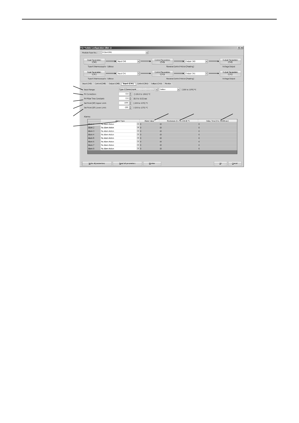
PID Module Configuration - Input Parameters Details
Input parameters for CH0 control are described here. Input parameters for CH1 control are the same as those
of CH0 control. However, the position from the control register for each parameter differs. For details about the
positions from the control register for CH1 control, see 5-17 to 5-20.
(1) Control Register+58: Input Range
Select input type and input range unit (Celsius or Fahrenheit). For details about the input range, see 6-10.
(2) Control Register+62: PV Correction
If the sensor cannot be installed to the location of the control target, the temperature measured by the sensor
may deviate from the actual temperature of the control target. When a target is controlled with multiple PID
modules, the measured temperatures may not match due to the differences in sensor accuracy or dispersion
of load capacities even though the set points (SP) of those PID modules are the same. In such cases, the
process variable (PV) of the PID module can be adjusted to the desired temperature by using the PV
Correction. The process variable (PV) after the PV correction should be within the control range (See 9-4). For
example, when type K thermocouple (-200 to 1370°C) is selected as input type, configure an appropriate PV
correction value so that the process variable (PV) after the PV correction does not exceed the control range
(-250 to 1420°C) [(Input range lower limit - 50°C) to (Input range upper limit + 50°C)].
When the process variable (PV) after the PV correction is within the control range, the PID module controls the
temperature based on the process variable (PV) after the PV correction. When the process variable (PV) after
the PV correction is out of the control range, the under or over range error occurs and the control output is
turned off
The process variable (PV) after the PV correction can be calculated using the following formula:
Process variable (PV) after the PV correction = Process variable (PV) + (PV correction value)
Example 1: When process variable (PV) is 198°C
If the PV correction value is 2.0°C, the process variable (PV) will be 200.0°C (198°C + 2.0°C).
If the PV correction value is -2.0°C, the Process variable (PV) will be 196.0°C (198°C - 2.0°C).
(1)
(2)
(3)
(4)
(5)
(6)
(7)
(8)
(9)