IDEC MicroSmart Pentra User Manual
Page 53
D
EVICE
A
LLOCATION OF
PID
M
ODULE
5-12
FC5A MicroS
mart PID Module User’s Manual FC9Y-B1283
0
0
1
2
0
1
2
0
1
2 0
1 2
1
0
1
0
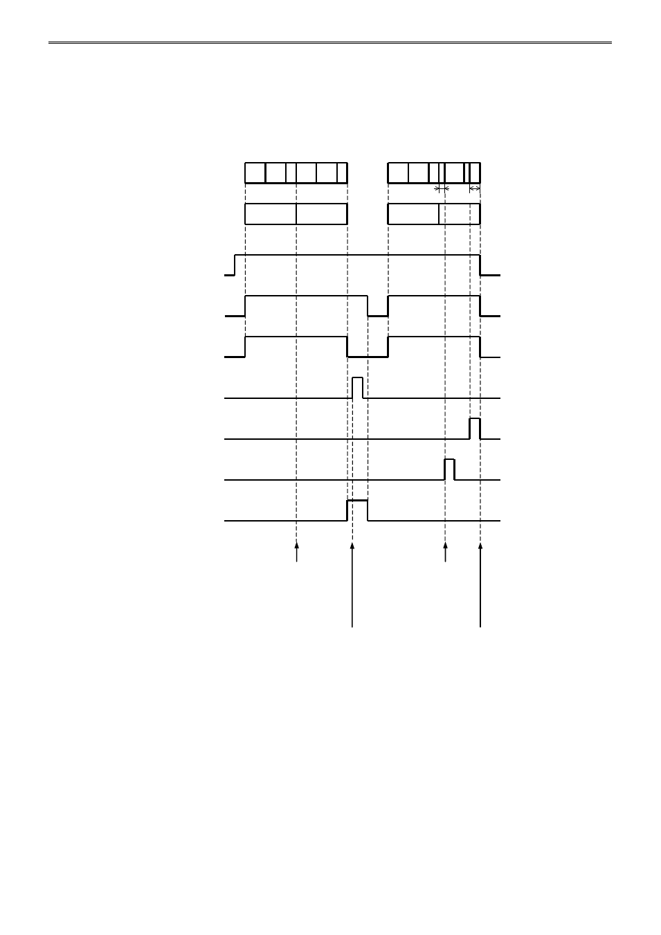
Example 2: Continue Program Control (Repeat) when Program Ends
The following diagram shows an example of the program control when continue program control (repeat) is
selected as the program end action.
Time of steps: Step 0 and 1: 60 minutes, Step 2: 30 minutes, Steps 3 to 9: 0 minute
Number of repeats: 1
In this example, D1000 is allocated to the control register and M500 is allocated to control relay.
Current step number
D1006
Number of repeats remaining
D1007
30 min
20 sec
Control enable bit
D1022.0
Program control bit
D1022.3
Program control bit
(Monitor)
D1009.3
Program hold bit
D1022.4
Advance next step bit
D1022.6
Advance previous step bit
D1022.7
Program end output
D1010.6
After the steps 0 to 2 are
executed, the program control is
repeated from the step 0.
While the program hold is executed
after the program end output is turned
on, the program hold bit has no effect.
The program control is not
moved back to step 2 even if
the advance previous step is
executed in step 0.
If the control is disabled
when step 2 is terminated,
the program end output
does not turn on.
ON
OFF
ON
OFF
ON
OFF
ON
OFF
ON
OFF
ON
OFF
ON
OFF