IDEC MicroSmart Pentra User Manual
Page 130
A
PPLICATION
E
XAMPLES
FC5A MicroSmart PID Module User’s Manual FC9Y-B1283
7-9
PID Module Parameter Configuration
The parameters of the PID module can be configured in the Expansion Modules Configuration and PID
Module Configuration dialog boxes. The procedure to configure the PID module is described below.
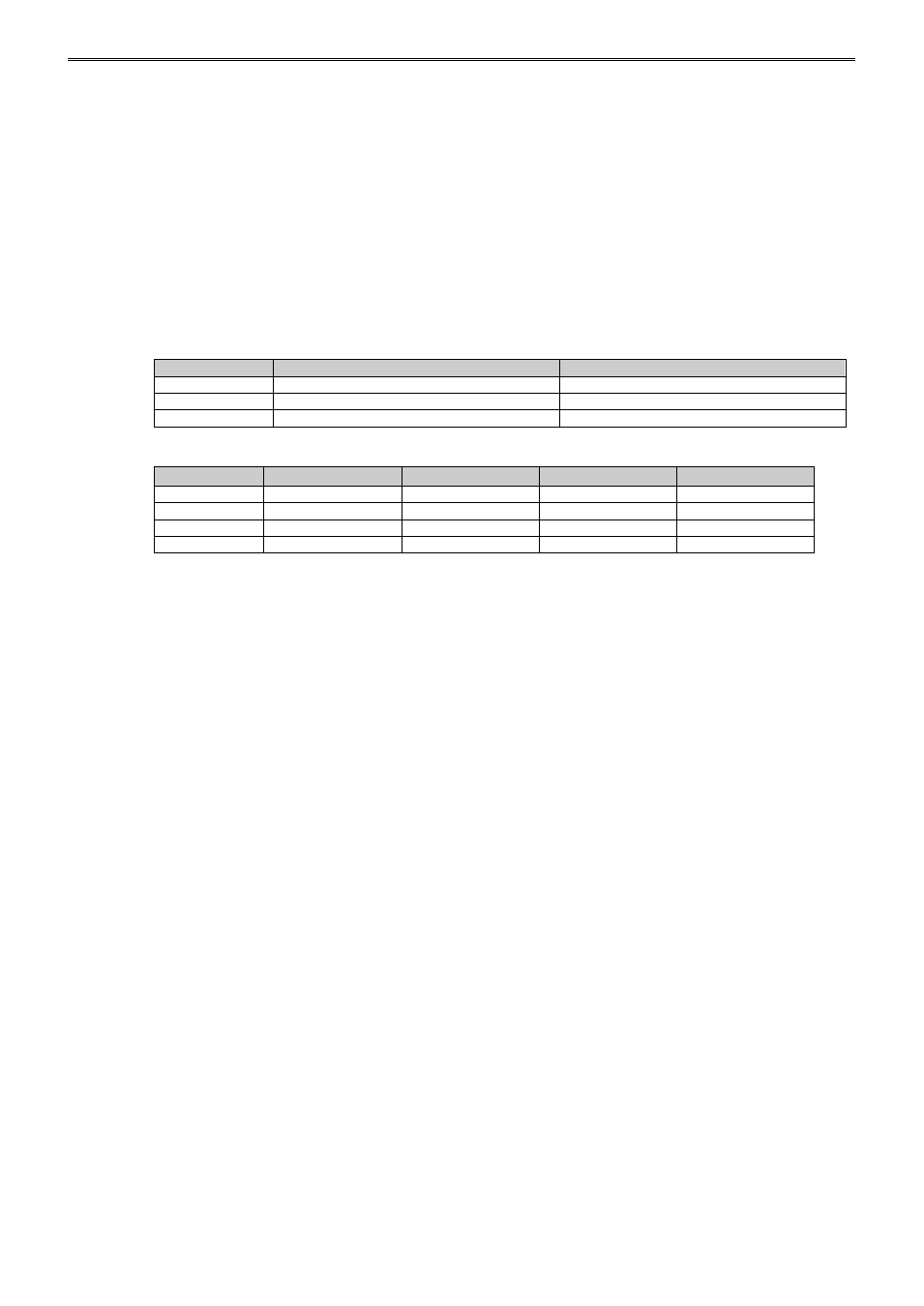
Parameter Configuration Example
Quantity of Modules: 1 unit
Slot No.:
Slot 1
Module Type No.:
FC5A-F2MR2
Data Register:
D1000
Internal Relay:
M1000
I/O Function:
Used as a 2-channel PID module
CH0
CH1
Input
Type K thermocouple (-200 to 1370)°C
Type K thermocouple (-200 to 1370)°C
Output
Relay output
Relay output
Alarm 1 Type
Upper limit alarm
Upper limit alarm
Program Pattern: Settings are common between CH0 and CH1.
Step 0
Step 1
Step 2
Step 3
Set Point (SP)
100°C
100°C
800°C
800°C
Step Time
60 minutes
60 minutes
300 minutes
30 minutes
Wait Value
10°C
0°C
10°C
0°C
Alarm 1 Value
0°C
10°C
0°C
10°C