IDEC MicroSmart Pentra User Manual
Page 59
D
EVICE
A
LLOCATION OF
PID
M
ODULE
5-18
FC5A MicroS
mart PID Module User’s Manual FC9Y-B1283
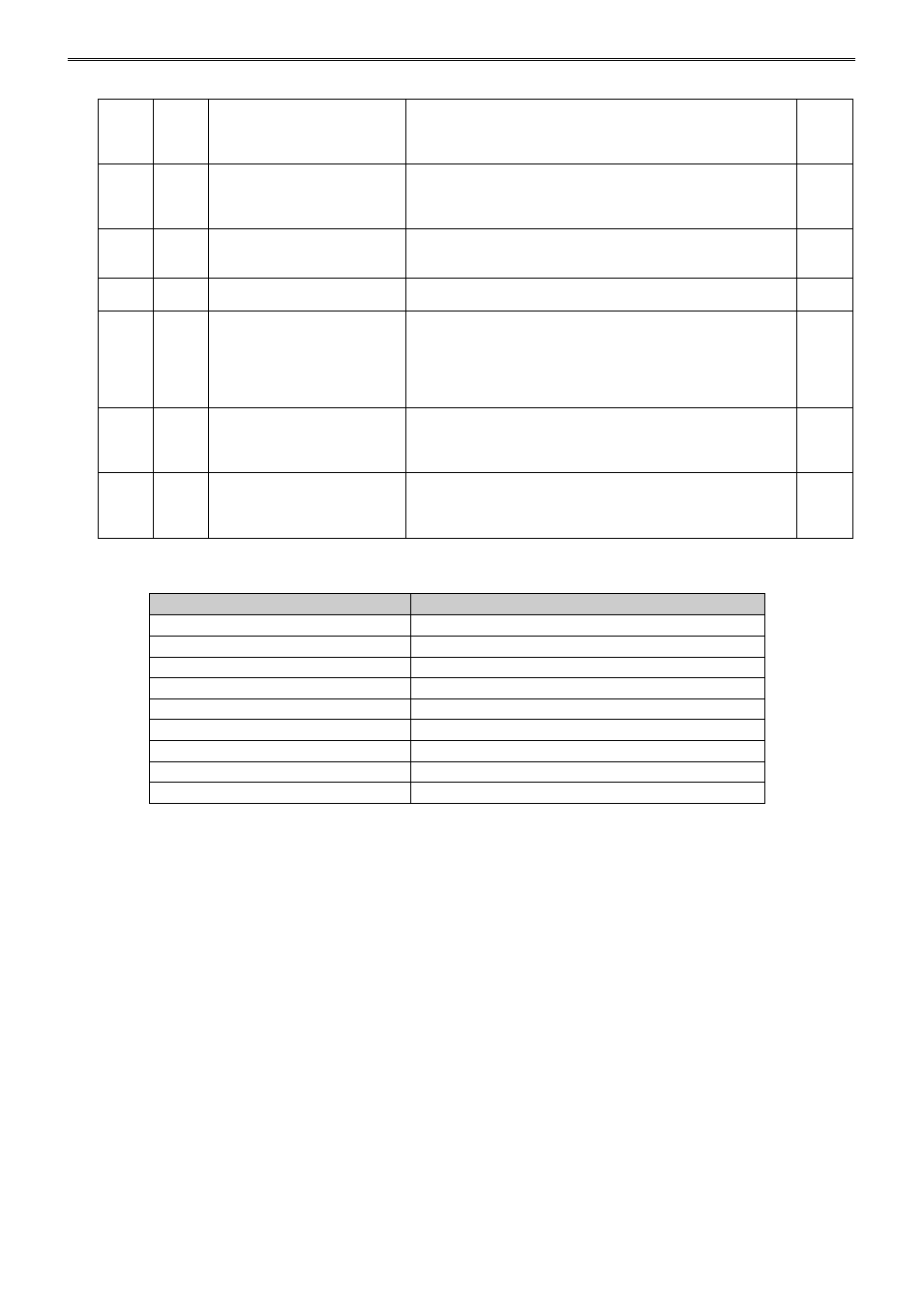
+46
+123
Output Manipulated Variable
Upper Limit
When output type is relay or voltage:
Output manipulated variable lower limit to 100%
When output type is current:
Output manipulated variable lower limit to 105%
R/W
+47
+124
Output Manipulated Variable
Lower Limit
When output type is relay or voltage:
0% to output manipulated variable upper limit
When output type is current:
-5% to output manipulated variable upper limit
R/W
+48
+125
Cooling Proportional Band
(CH0 only)
0.0 to 10.0 times
(Cooling proportional band is the multiplication of heating
proportional band)
R/W
+49
+126
Cooling Control Period
(CH0 only)
1 to 120 sec
R/W
+50
+127
Overlap/Dead Band
(CH0 only)
When input range unit is Celsius:
-200.0 to 200.0°C
When input range unit is Fahrenheit:
-200.0 to 200.0°F
When input is voltage or current input:
-2000 to 2000
R/W
+51
+128
Cooling Output Manipulated
Variable Upper Limit
(CH0 only)
When output type is relay or voltage:
Cooling output manipulated variable lower limit to 100%
When output type is current:
Cooling output manipulated variable lower limit to 105%
R/W
+52
+129
Cooling Output Manipulated
Variable Lower Limit
(CH0 only)
When output type is relay or voltage:
0% to cooling output manipulated variable upper limit
When output type is current:
-5% to cooling output manipulated variable upper limit
R/W
Valid Range for Alarm 1 to Alarm 8 Settings
*1: When input is voltage/current, full scale is the linear conversion span.
*2: When input is voltage/current, the valid range is the linear conversion minimum value to linear conversion
maximum value.
Alarm Type
Valid Range
Upper Limit Alarm
–(Full scale) to full scale *1
Lower Limit Alarm
–(Full scale) to full scale *1
Upper/Lower Limits Alarm
0 to full scale *1
Upper/Lower Limit Range Alarm
0 to full scale *1
Process High Alarm
Input range lower limit to input range upper limit *2
Process Low Alarm
Input range lower limit to input range upper limit *2
Upper Limit Alarm with Standby
–(Full scale) to full scale *1
Lower Limit Alarm with Standby
–(Full scale) to full scale *1
Upper/Lower Limits Alarm with Standby
0 to full scale *1