Installation and wiring, Nstallation and, Iring – IDEC MicroSmart Pentra User Manual
Page 18: Caution
I
NSTALLATION AND
W
IRING
FC5A MicroSmart PID Module User’s Manual FC9Y-B1283
3-1
3: I
NSTALLATION AND
W
IRING
This chapter describes how to install and wire the PID modules. For general methods and precautions for
installation and wiring of the PID modules, see chapter 3 in the FC5A MicroSmart user
’s manual (FC9Y-B1268).
Be sure to use the PID modules properly after understanding installation and wiring thoroughly.
Caution
• Assemble the CPU module and PID modules before installing them on a DIN rail.
Otherwise, they may break.
• Do not lay out or wire the modules while power is supplied to them. Otherwise, they
may be damaged.
• When installing modules, follow the instructions described in the FC5A MicroSmart
user
’s manual. If there are flaws in the installation, it may cause disattachment,
failure or malfunction.
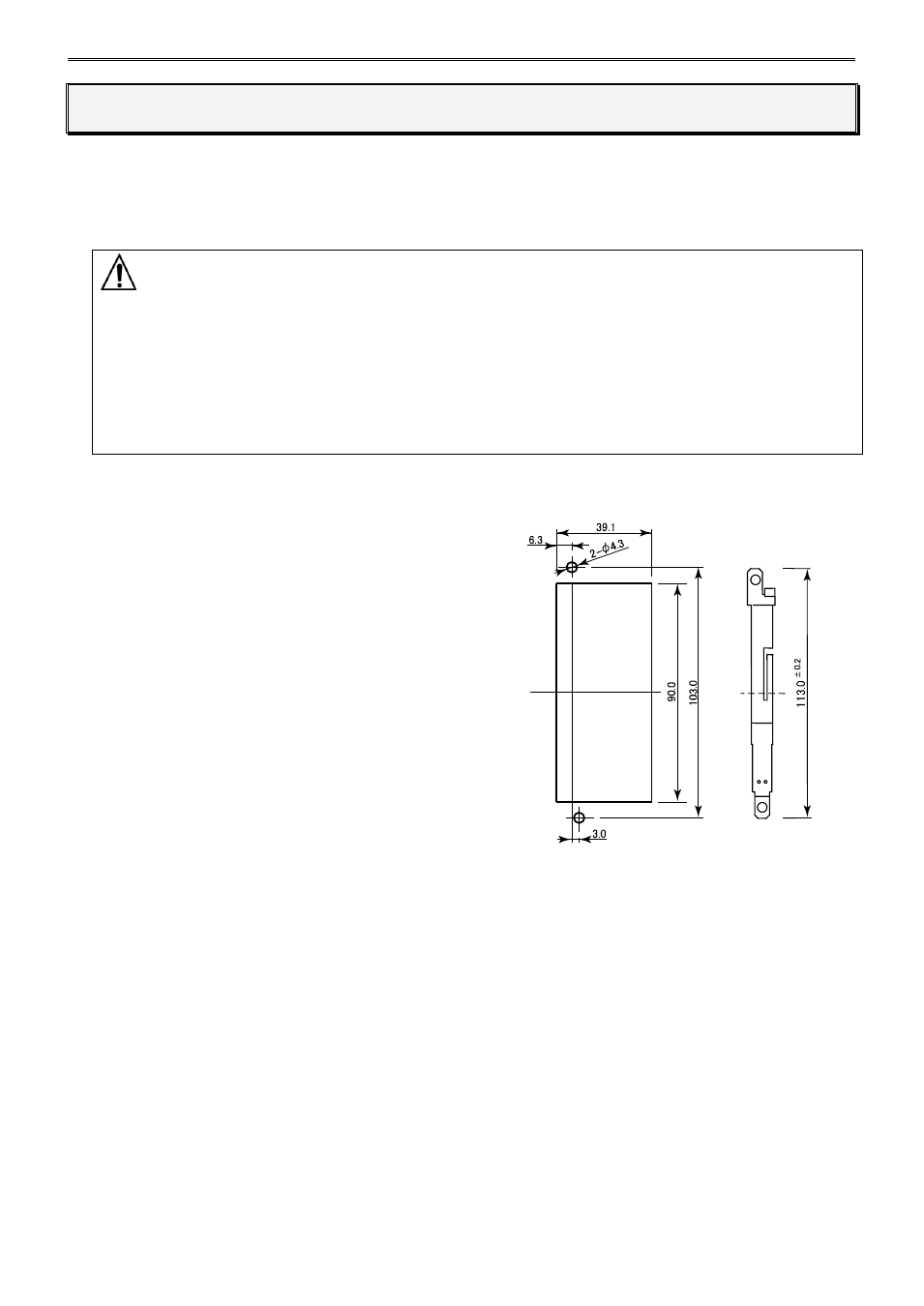
Mounting Hole Layout for Direct Mounting on Panel Surface
To mount the PID module on a panel surface,
use the direct mounting strip and two M4 screws
(6 or 8 mm long).
For details about the direct mounting strip, see the
FC5A MicroSmart user
’s manual (FC9Y-B1268).
(All dimensions in mm)
Direct mounting strip
FC4A-PSP1P