IDEC MicroSmart Pentra User Manual
Page 109
C
ONFIGURING
PID M
ODULE USING
W
IND
LDR
6-44
FC5A MicroSmart PID Module User’s Manual FC9Y-B1283
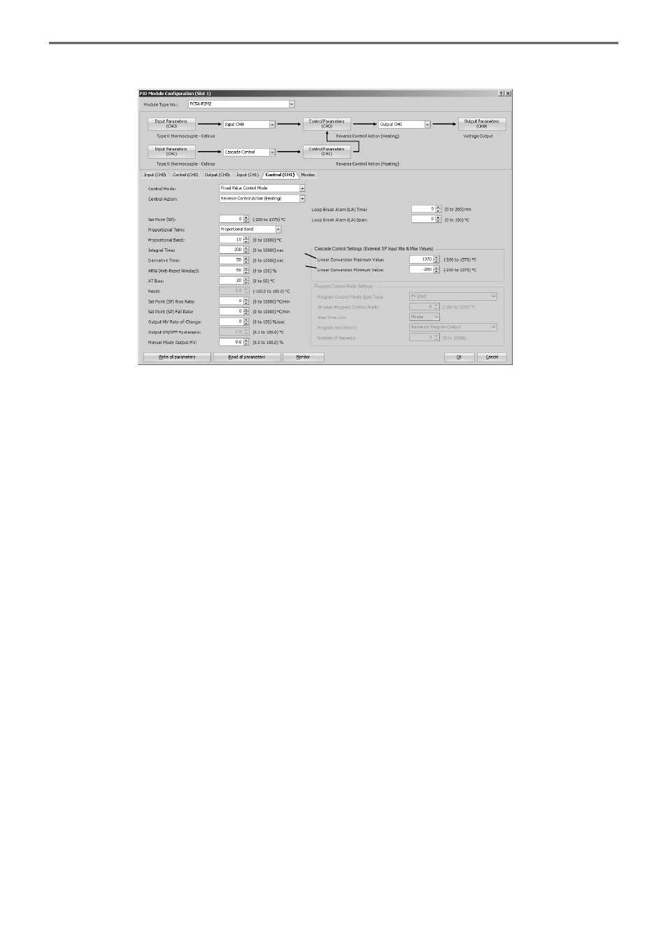
Control Parameters when Cascade Control is Selected
(1) Control Register+178: External SP Input Linear Conversion Maximum Value
Configure the external SP input linear conversion maximum value for the cascade control. The output
manipulated variable (MV) (0 to 100%) of the master (CH1) corresponds to the set point (SP) of the slave
(CH0). The range of the set point (SP) of the slave (CH0) is the external SP input linear conversion minimum
value to the external SP input linear conversion maximum value.
Configure the external SP input linear conversion maximum value for when the output manipulated variable
(MV) of the master (CH1) is 100%.
(2) Control Register+179: External SP Input Linear Conversion Minimum Value
Configure the external SP input linear conversion minimum value for the cascade control. The output
manipulated variable (MV) (0 to 100%) of the master (CH1) corresponds to the set point (SP) of the slave
(CH0). The range of the set point (SP) of the slave (CH0) is the external SP input linear conversion minimum
value to the external SP input linear conversion maximum value.
Configure the external SP input linear conversion minimum value for when the output manipulated variable
(MV) of the master (CH1) is 0%.
(1)
(2)