Pid m – IDEC MicroSmart Pentra User Manual
Page 73
C
ONFIGURING
PID M
ODULE USING
W
IND
LDR
6-8
FC5A MicroSmart PID Module User’s Manual FC9Y-B1283
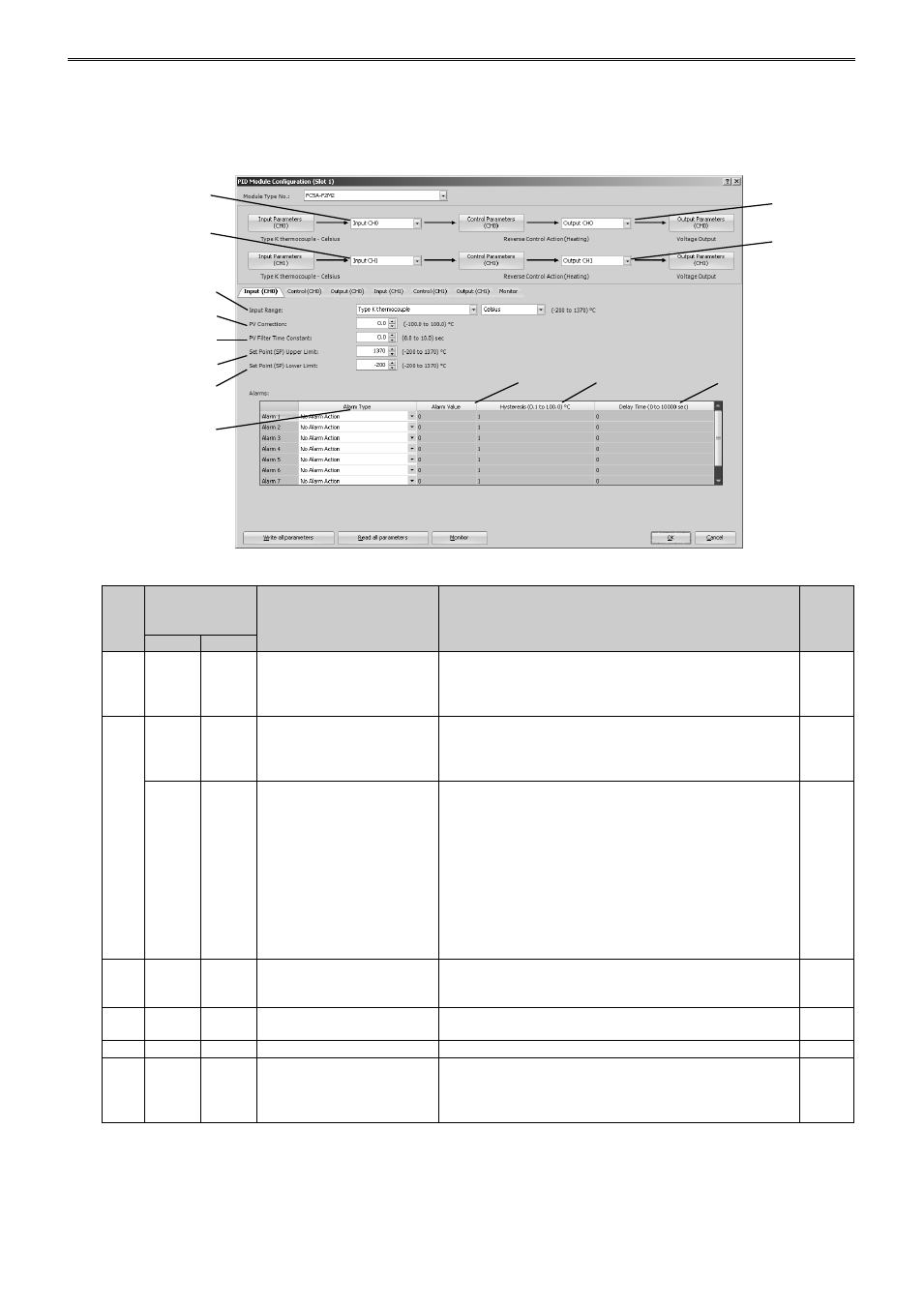
PID Module Configuration - Input Parameters List (CH0 and CH1)
The input parameters for CH0 and CH1 controls are described here.
Control Registers
Offset from
the control
register
Parameter
Description
R/W
CH0
CH1
(1)
+56
–
Input CH0 Function
0: Input CH0
1: Difference input (Input CH0 - Input CH1)
2: Difference input (Input CH1 - Input CH0)
3: Addition input (Input CH0 + Input CH1)
R/W
(2)
–
+133
Input CH1 Function
0: Input CH1
1: Difference input (Input CH0 - Input CH1)
2: Difference input (Input CH1 - Input CH0)
3: Addition input (Input CH0 + Input CH1)
R/W
+55
–
External SP Input
0: Disabled
1: External SP input (4 to 20mA DC) (Note)
2: External SP input (0 to 20mA DC)
3: External SP input (1 to 5V DC)
4: External SP input (0 to 1V DC)
5: Cascade control (Note)
Note: When External SP input is selected in Input CH1
Function,
“1: External SP input (4 to 20mA DC)” is
selected as the default. When Cascade Control is
selected in Input CH1 Function,
“5: Cascade control” is
selected.
R/W
(3)
+57
–
Output CH0 Function
0: Output CH0
1: Output CH1
2: Both outputs (Output CH0, Output CH1)
R/W
(4)
–
+134
Output CH1 Function
0: Output CH1
(The selection of Output CH0 Function has priority.)
R/W
(5)
+58
+135
Input Range
See page 6-10 for the detail about the input range.
R/W
(6)
+59
+136
Set Point (SP) Upper Limit/
Linear Conversion
Maximum Value
When input is thermocouple/resistance thermometer:
Set point (SP) lower limit to input range upper limit
When input is voltage/current:
Linear conversion minimum to input range upper limit
R/W
(1)
(2)
(3)
(4)
(5)
(6)
(7)
(8)
(9)
(10)
(11)
(12)
(13)