IDEC MicroSmart Pentra User Manual
Page 123
A
PPLICATION
E
XAMPLES
7-2
FC5A MicroSmart PID Module User’s Manual FC9Y-B1283
PID Module Parameter Configuration
The parameters of the PID module can be configured in the Expansion Modules Configuration and PID
Module Configuration dialog boxes. The procedure to configure the PID module is described below.
Parameter Configuration Example
Quantity of Modules: 1 unit
Slot Number:
Slot 1
Module Type No.:
FC5A-F2M2
Data Register:
D1000
Internal Relay:
M1000
I/O Function:
Used as a 2-channel PID module
CH0
CH1
Input
Type K thermocouple (-200 to 1370)°C
Type K thermocouple (-200 to 1370)°C
Output
Non-contact voltage output (for SSR drive)
Non-contact voltage output (for SSR drive)
Alarm 1 Type
Upper limit alarm
Upper limit alarm
Alarm 1 Value
5°C
5°C
Set Point (SP)
200°C
210°C
Control Action
PID control action [P, I, D and ARW are
automatically calculated using auto-tuning
(AT)]
PID control action [P, I, D and ARW are
automatically calculated using auto-tuning
(AT)]
AT Bias
20°C
20°C
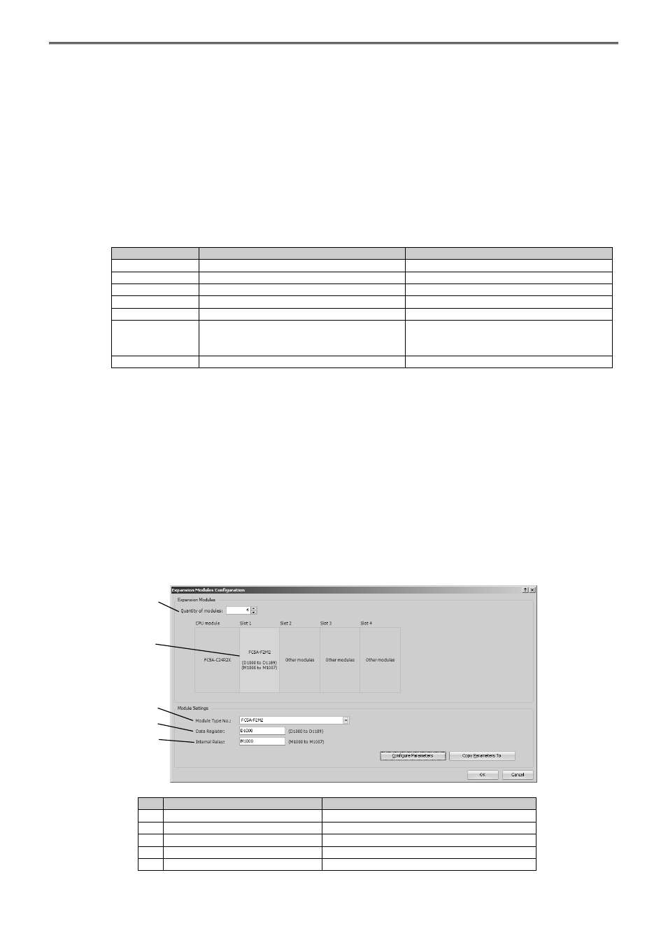
Parameter Configuration Procedure
1. Expansion Modules Configuration
Select Configuration > Expansion Modules from the WindLDR menu bar to open the Expansion
Modules Configuration dialog box.
In the Expansion Modules Configuration dialog, configure the quantity of modules, slot number, module
type number, control register (data register) and control relay (internal relay). Click on Configure
Parameters button to open the PID Module Configuration dialog box.
Expansion Modules Configuration Dialog Box
Item
Setting
(1)
Quantity of Modules
1
(2)
Slot No.
Slot 1
(3)
Module Type No.
FC5A-F2M2
(4)
Data Register
D1000
(5)
Internal Relay
M1000
(1)
(2)
(3)
(4)
(5)