Solare Datensysteme Solar-Log User Manual
Page 65
65
Other connections
13�2 Relay (only Solar-Log 1000, 1200 and 2000)
The Solar-Log™ has a potential-free control relay, which is activated under the following conditions:
•
Alarm contact triggered
•
Active power reduction activated
•
Optimization of self-consumption
The relay may be loaded with a maximum of 24 V DC and max. 2 A / ohm resistive load.
A 230 V appliance must be connected via another load relay.
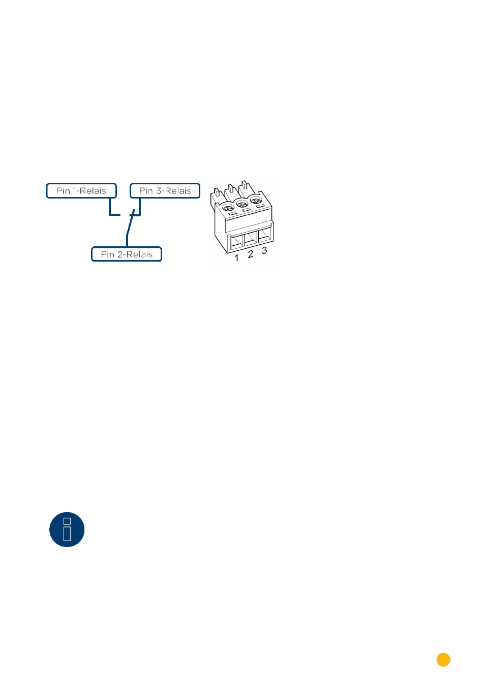
Connection
Fig.: Relay connection diagram
Wiring
The wiring is done using the supplied 3-pin connector;
usually pin 1 and pin 2 are used.
In the Off state,
•
pin 1-2 are open
•
and pin 2-3 are closed.
In the On state (alarm/fault/power reduction activated),
•
and pin 1-2 are closed.
•
pin 2-3 are open
13�3 USB
Solar-Log™ 300, 1000, 1200 and 2000 have a USB connection. This USB connection can only be used for
USB sticks and not for a direct PC connection.
Note
When a USB stick is connected, the Solar-Log™ automatically saves a backup in the
backup folder. A maximum of 10 backup files are saved in the directory. Older backup
files are automatically deleted.
The backup is saved on the USB stick in the directory /Backup with the following file names:
•
solarlog_backup_YYMMDD.dat
YYMMDD = year, month and day - each two digits, e.g.
140312 is then 12 March 2014