Solare Datensysteme Solar-Log User Manual
Page 146
146
Special functions
versions can be configured.
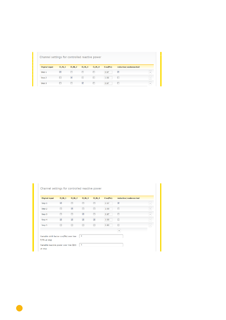
Ripple control receivers generally possess 2 to 5 relays. The assignment of the individual relay states for a
particular shift factor is specified by the respective grid operator and stored in the Solar-Log™ using this
matrix. In this way the connected inverters can be adjusted to meet the specified reduction levels.
Fig.: Channel settings for remote controlled cos (Phi)
For each level, the input signal combination and a value for the shift factor in cos (Phi) is entered.
Checking the box next to the digital inputs of the PM+ interface (D_IN_1 to D_IN_4) means that the input is
supplied with 5V from pin 6 to reduce the output on the cos phi defined in the box "cos (Phi)".
Four levels are shown in the basic setting. The "+" sign can be used to extend the list by additional levels.
Procedure:
•
Select
remote controlled.
•
Select the
interface
of the inverter that is to be reduced.
•
Enter the channel settings for power reduction
according to the specifications and wiring
.
•
Select options.
•
SAVE settings.
More Options.
Switching from the remote-controlled cos (Phi) to the possible characteristic curves can be implemented
via assigned combinations of signals to the PM+ interface.
Fig.: Switching to reactive power characteristic curves with certain signals
If a switch to the characteristic curve operating mode (P/Pn and Q(U)) is required due to a certain ripple
control receiver signal, the respective levels for the switch can be entered in the input box. If no switch
should take place, enter 0 in the input box.