4 inverter as part of a pv system – KACO Powador 30.0 - 60.0 TL3 User Manual
Page 9
Description
Operating Instructions for Powador 30.0-72.0 TL3_EN
Page 9
EN
3.1.4
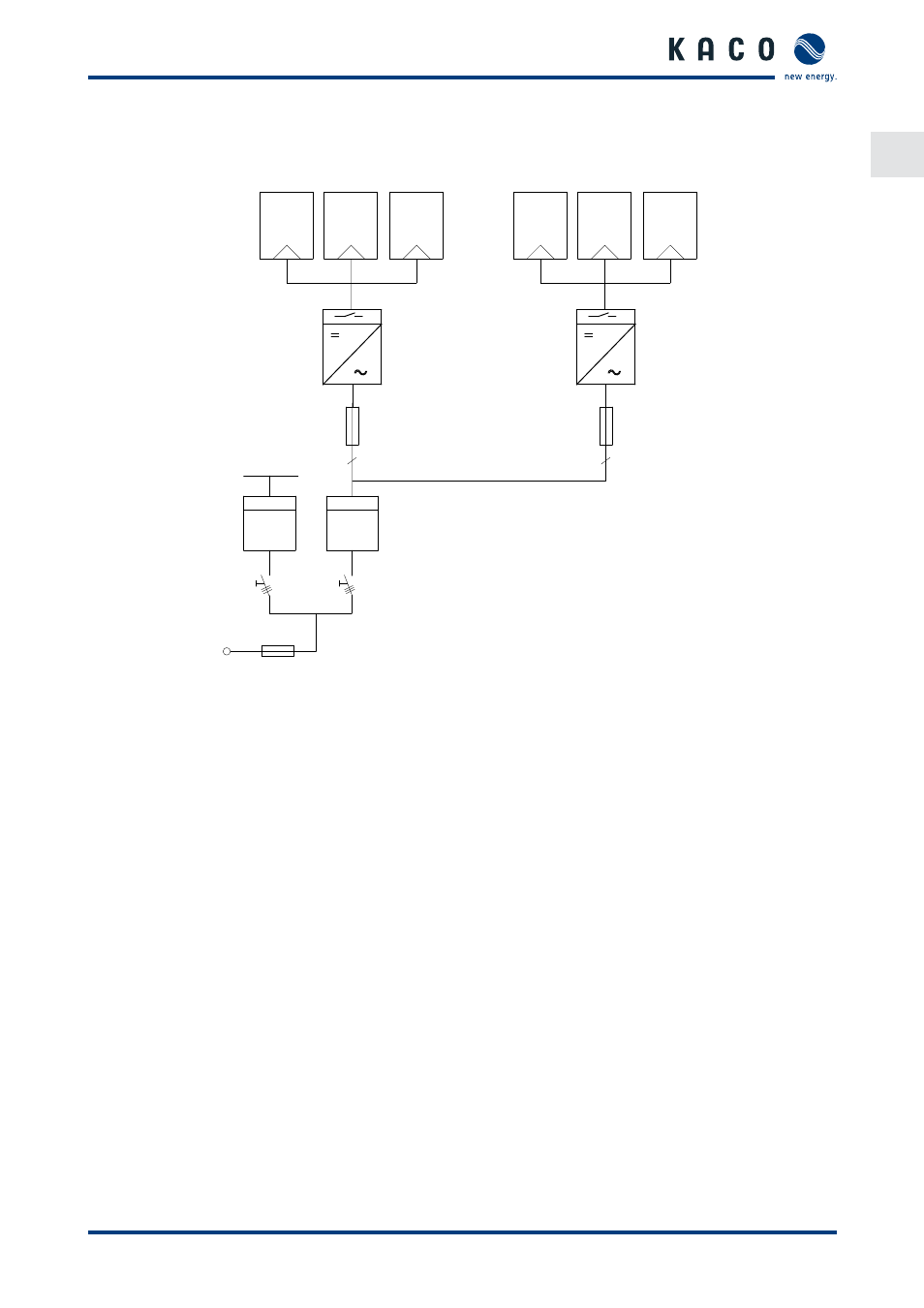
Inverter as part of a PV system
KWh
KWh
PV generator
PV generator
Inverter with
DC isolator switch
Inverter with
DC isolator switch
Line protection
Line protec-
tion
Load
Feed-in meter
Reference
counter
Main switch
Grid connection point
Selective main switch
Figure 2: Circuit diagram of a system with two inverters
3.1.4.1
Summary of the components
PV generator
The PV generator converts sunlight radiation into electrical energy.
DC terminal point
Options for parallel connections of several generator strings:
•
To a DC terminal point between the DC generator and inverter
•
Directly to the inverter (terminals for 12 (3 x 4) strings are provided on the inverter),
•
Directly to the PV generator with a positive and negative lead to the inverter
DC isolator switch
Use the DC isolator switch to disconnect the inverter from all power sources on the PV generator side.
Grid fuses
Use only specifi c PV rated fuses.
Feed-in meter
The feed-in meter is specifi ed and installed by the power supply company. Some power supply companies also
allow the installation of your own calibrated meters.
Selective main switch
If you have any questions about the selective main switch, contact your power supply company.