KACO Powador 30.0 - 60.0 TL3 User Manual
Page 27
Installing the inverter
Operating Instructions for Powador 30.0-72.0 TL3_EN
Page 27
EN
Authorised electrician
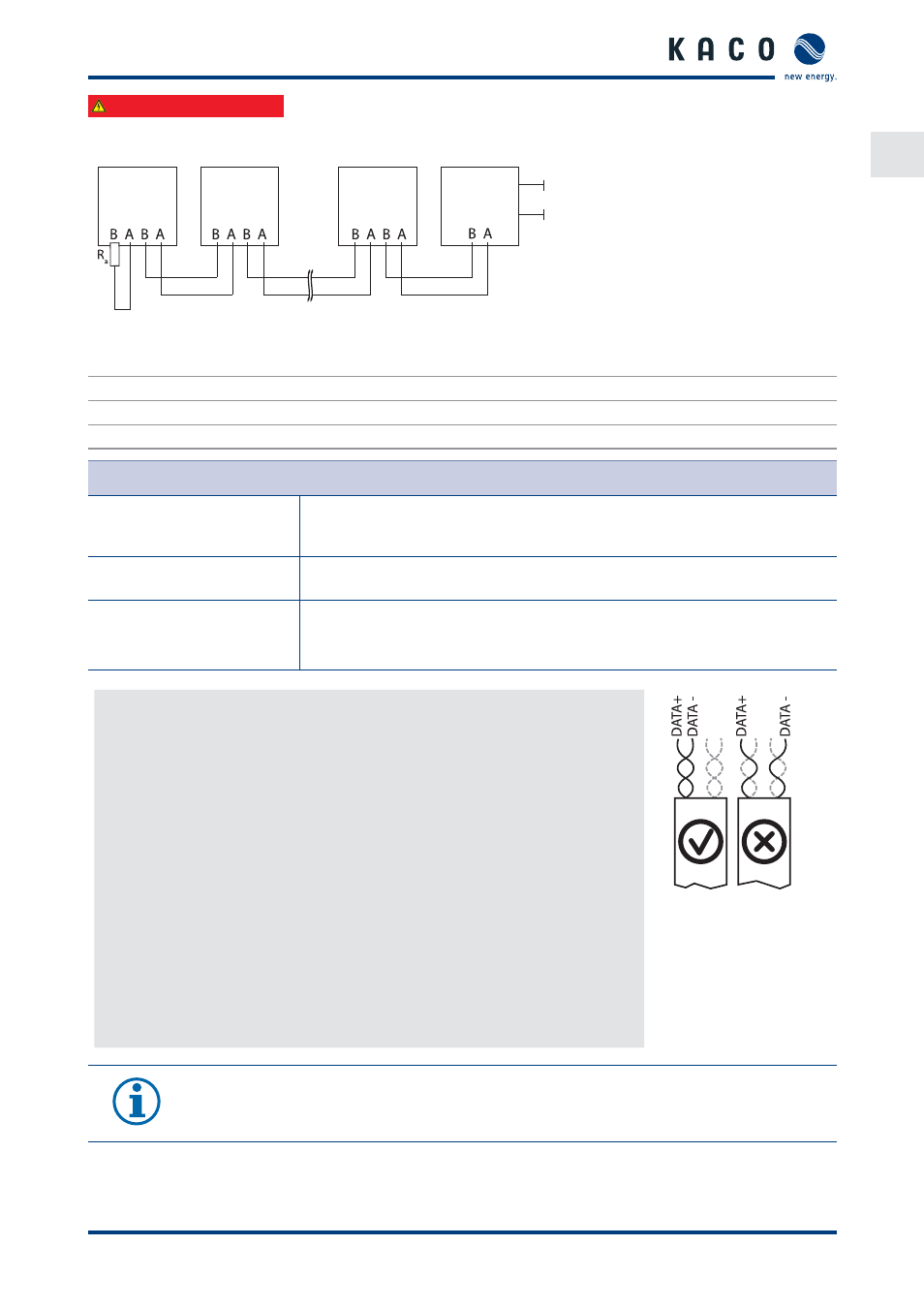
7.4.5.1 Wiring
diagram
1
2
2
3
4
5
Figure 24: RS485 interface wiring diagram
Key
1
Inverter, terminal unit
4
Communication
2
Inverter
5
230 V AC
3
Powador-proLOG
Properties of the RS485 data line
Maximum length of the RS485
bus line
The maximum allowed length of the RS485 bus is 1200 m.
This length can be reached only under optimum conditions.
Cable lengths exceeding 500m generally require a repeater or a hub.
Maximum number of
connected bus devices
31 inverters + 1 data monitoring unit
Data line
Twisted, shielded. Recommendations:
LI2YCYv (twisted pair) black for laying cable outside and in the ground, 2 x 2 x 0.5
LI2YCY (twisted pair) grey for dry and damp indoor spaces, 2 x 2 x 0.5
Connecting the RS485 bus
To prevent interference during data transmission:
•
Observe the wire pairing when connecting DATA+ and DATA- (siehe FigureFigure
25)
•
Do not lay RS485 bus lines in the vicinity of live DC/AC cables.
1.
Unscrew the cable fi tting.
2. Thread the connection cables through the cable fi tting.
3. Connect the connection cables to the corresponding connection terminals (see
Figure 23 on page 25).
4. The following must be connected to all inverters and to the data monitor unit
in the same way:
–
Wire A (-) to wire A (-) and
–
Wire B (+) to wire B (+) (see Figure 24 on page 27)
5. Tighten the cable fi tting.
6. Activate the terminating resistor on the terminal unit.
Figure 25: Assignment of
twisted-pair wires
NOTE
When using the RS485 bus system, assign a unique address to every bus device (inverter, sensor) and
terminate the terminal units (see the “Settings” menu) .