1 connect the device to the power grid – KACO Powador 30.0 - 60.0 TL3 User Manual
Page 20
Installing the inverter
Page 20
Operating Instructions for Powador 30.0-72.0 TL3_EN
EN
EN
Authorised electrician
DC connection terminals
3 (1 per MPP tracker)
30.0-60.0 TL3: 12 (4 per MPP tracker)
72.0 TL3: 15 (5 per MPP tracker)
72.0 TL3 F-variant : 12 (4 per MPP tracker)
7.3.1
Connect the device to the power grid
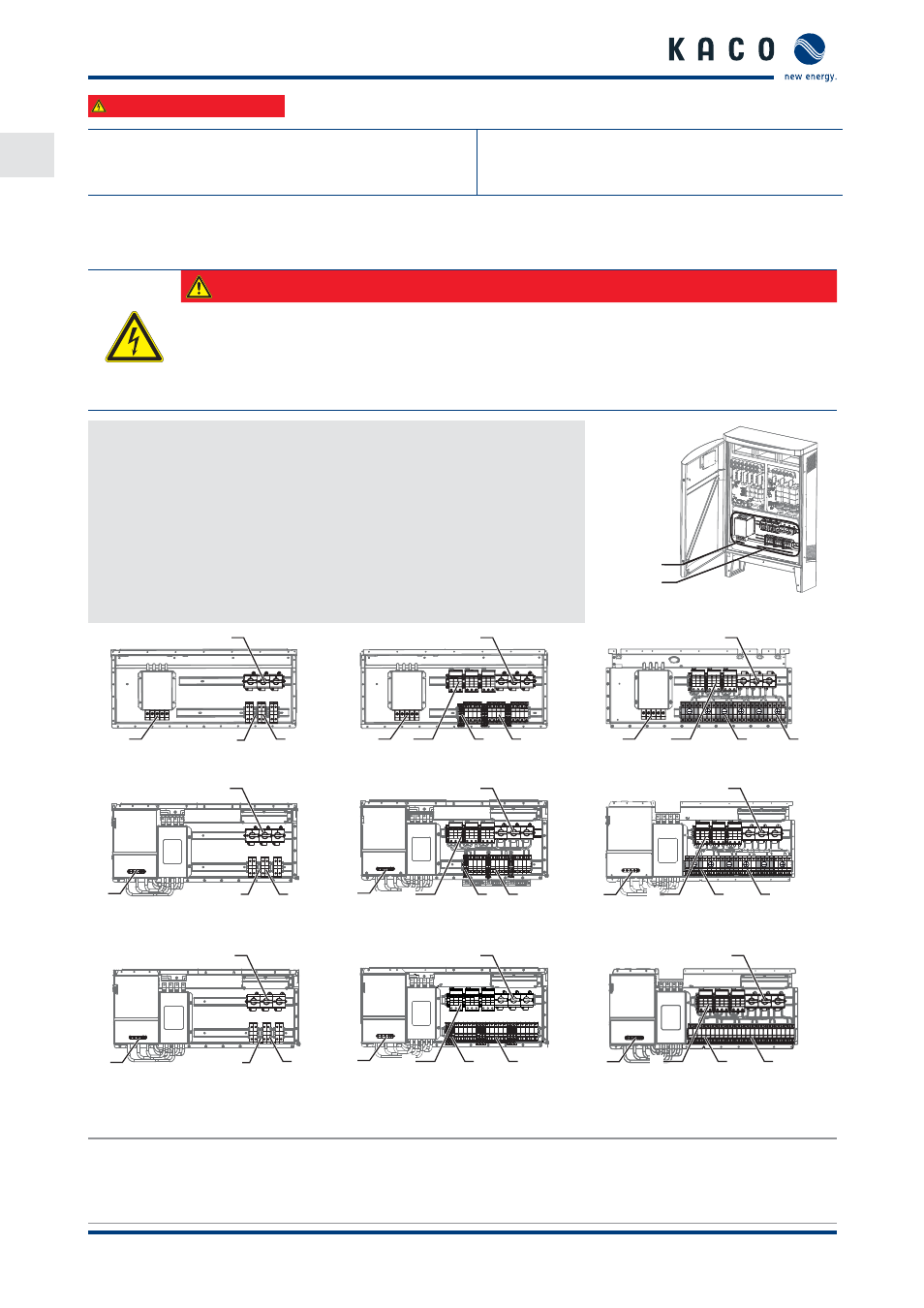
The power connection wires are connected to the AC terminal in the left connection area (see Figure 10).
DANGER
Risk of fatal injury due to electric shock
Severe injury or death will result if the live connections are touched.
›
Switch off all power sources to the inverter before you insert the grid power cable into the unit.
›
Isolate before carrying out work on the public power supply and the system power supply.
Prepare the grid connection
↻ Use 5 core cable (L1 brown, L2 black, L3 grey, N blue, PE green/yellow)
or 4 core cable (L1 brown, L2 black, L3 grey, PE green/yellow).
1.
Loosen cable fi tting for AC connection.
2. Remove the outer cladding of the AC cables.
3. Insert the AC cables through the cable fi tting into the connection area.
4. Strip the insulation from the AC cables.
5. Making the grid connection
AC side
DC-side
Figure 10: Connection terminals
1
2
3a
3c
1
2
3a
4
3c
1
2
3a
4
3b
Figure 11: Powador 30.0-48.0 TL3 - M
Figure 12: Powador 30.0-48.0 TL3 - XL
Figure 13: Powador 30.0-48.0 TL3 - XL- F*
2
3a
3c
1
2
3a
4
3c
1
2
3a
4
3b
1
Figure 14: Powador 60.0 TL3 - M
Figure 15: Powador 60.0 TL3 - XL
Figure 16: Powador 60.0 TL3 - XL - F*
2
3a
3c
1
2
3a
4
3c
1
2
3a
4
3b
1
Figure 17: Powador 72.0 TL3 - M
Figure 18: Powador 72.0 TL3 - XL*
Figure 19: Powador 72.0 TL3 - XL - F*
Key
1
AC connection terminals
3
DC connection terminals
3a) Fuse block (DC+)
3b) Fuse block (DC-)
3c) Feed-through terminal (DC-)