Yaskawa Sigma-5 User Manual: MECHATROLINK-II Commands User Manual
Page 124
7.1 Main Command Data Field
7-5
7
Data Field
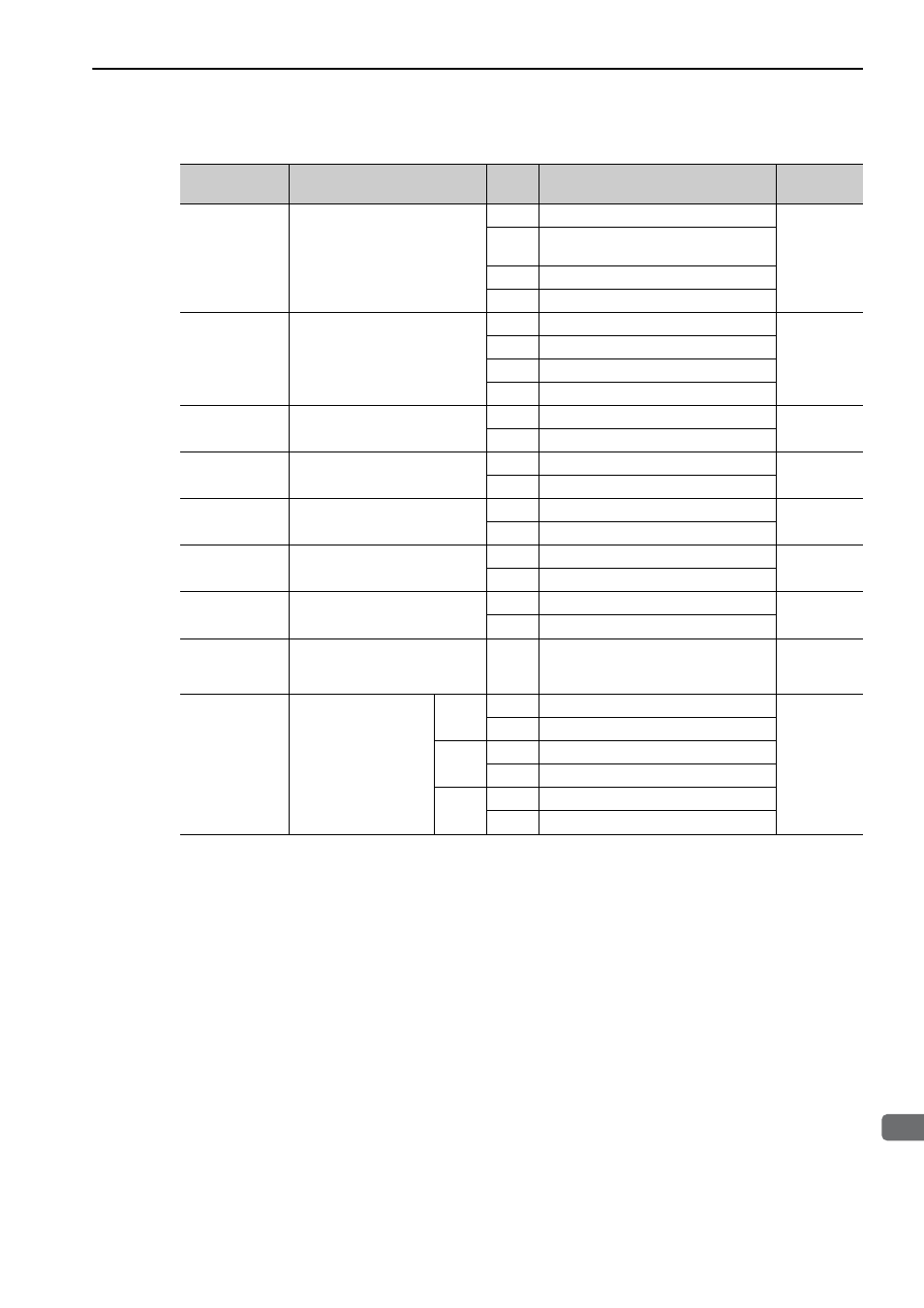
(3) Functions That Can Be Allocated to Bits of the OPTION Field
Note 1. Do not allocate more than one signal to one bit. Otherwise, multiple signals will be controlled by one bit.
2. The bits to which no function is allocated will act as it is set to 0 (zero).
3. To enable the OUT_SIGNAL function, set the following parameters to Zero: Pn50E, Pn50F, and Pn510.
Name
Description
Value
Details
Default
Setting
ACCFIL
(2 bits)
Acceleration/Deceleration filter
0
No acceleration/deceleration filter
D3, D4
1
Exponential function acceleration/decel-
eration
2
S-curve acceleration/deceleration
3
Do not set.
G_SEL
(2 bits)
Gain switching
0
First gain
D8, D9
1
Second gain
2
Reserved (invalid)
3
Reserved (invalid)
V_PPI
(1 bit)
Speed loop P/PI control
0
PI control
D12
1
P control
P_PI_CLR
(1 bit)
Position loop position integral
clear
0
Does not clear.
D13
1
Clears.
P_CL
(1 bit)
Forward torque (force) limit
0
Does not control torque (force).
D14
1
Controls torque (force).
N_CL
(1 bit)
Reverse torque (force) limit
0
Does not control torque (force).
D15
1
Controls torque (force).
LT_DISABLE
(1 bit)
Latch signal input disabled
0
Enables latch signal input.
Not allocated
1
Disables latch signal input.
BANK_SEL1
(4 bits)
Bank selector 1
(Bank for acceleration/decelera-
tion parameter switching)
0 to
15
Bank 0 to Bank 15
Not allocated
OUT_SIGNAL
(3 bits)
I/O signal output com-
mand
BIT 0
0
SO1 output signal OFF
Not allocated
1
SO1 output signal ON
BIT 1
0
SO2 output signal OFF
1
SO2 output signal ON
BIT 2
0
SO3 output signal OFF
1
SO3 output signal ON