3 state transition diagram, 3 state transition diagram -3 – Yaskawa Sigma-5 User Manual: MECHATROLINK-II Commands User Manual
Page 11
1.1 MECHATROLINK-II Communications
1-3
1
MECHA
TROLINK-
II
Commands
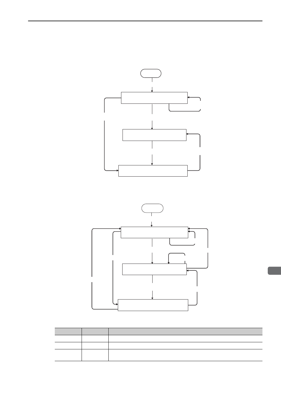
1.1.3 State Transition Diagram
The primary (master) and secondary (slave) station state transitions are shown in the following diagrams.
Primary Station (Master Station) State Transition
Secondary Station (Slave Station) State Transition
Phase
Abbreviation
Description
1
P1
Waiting for establishment of connection.
2
P2
Asynchronous communications enabled. Only asynchronous commands can be used.
3
P3
Synchronous communications enabled. Both synchronous and asynchronous commands
can be used.
P1/ Waits for connection establishment
P2/ Asynchronous communications state
P3/ Synchronous communications state
Sends CONNECT
(Asynchronous communications)
Sends SYNC_SET
Power ON
Start
Sends CONNECT
(Synchronous communications)
Communications
error
Communications
error
Start
P1/ Waits for connection establishment
P2/ Asynchronous communications state
P3/ Synchronous communciations state
Power ON
Sends SYNC_SET
Sends CONNECT
(Asynchronous communications)
Receives DISCONNECT
Receives CONNECT
Communications
error
Communications
error
Receives DISCONNECT
Communications
error