1 mechatrolink-ii communications, 1 layers, 2 frame structure – Yaskawa Sigma-5 User Manual: MECHATROLINK-II Commands User Manual
Page 10: 1 mechatrolink, 1 layers -2 1.1.2 frame structure -2, 1 mechatrolink-ii communications -2
1 MECHATROLINK-II Commands
1.1.1 Layers
1-2
1.1 MECHATROLINK-II Communications
1.1.1 Layers
The MECHATROLINK-II communications layers have functions equivalent to layers 1, 2, and 7 in the OSI
(Open System Interconnection) reference model.
This manual describes commands for the application layer.
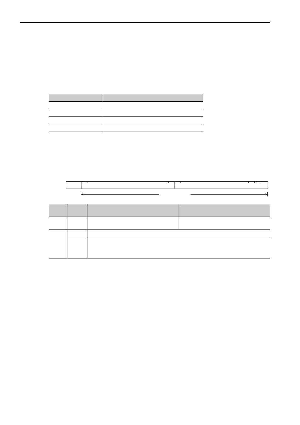
1.1.2 Frame Structure
A MECHATROLINK-II command is composed of a main command and a subcommand as shown below. It
can also be used only with a main command.
The application layer interfaces with only the information field.
OSI Reference Model and MECHATROLINK-II Model
OSI
MECHATROLINK-II
Layer 7: Application layer
MECHATROLINK-II application layer
Layers 3 to 6
None
Layer 2: Data link layer
MECHATROLINK-II data link layer
Layer 1: Physical layer
MECHATROLINK-II physical layer
Classifi-
cation
Byte
Command
Response
Control
Field
0
03H (Fixed)
01H (Fixed)
Informa-
tion
Field
1 to 16 Used by main command.
17 to 31
Used by subcommands. The subcommands for servo drives use only 17th to 29th byte. Therefore,
only 17th to 29th byte are described in this manual.
Note: In some main commands, subcommand cannot be used.
Control
field
Main command area
Subcommand area
30
29
17
16
1
0
Byte
31
Information field