Caution – Yaskawa 120 Series I/O Modules User Manual
Page 83
3.2 Digital Output Module Specifications
3-53
3
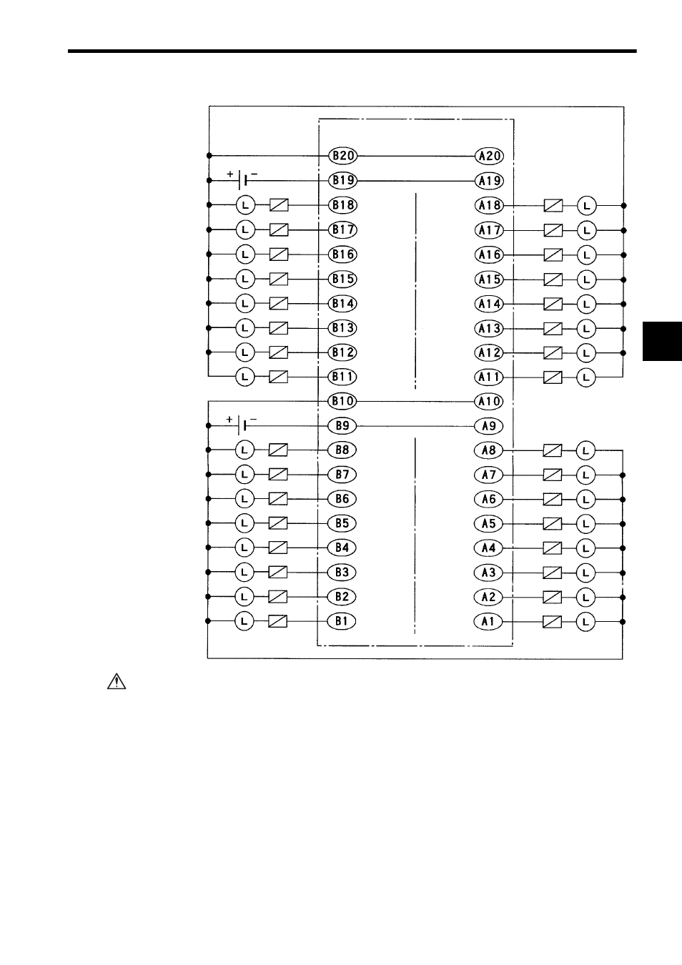
If using a 12/24-VDC 64-point Output Module, connect a fuse, which complies with
the load specifications, in series with the load.
A protective fuse built into the following 12/24-VDC 64-point Output Modules
does not protect the output element. If a fuse is not connected, a fire or dam-
age to the devices or output circuits may occur if the load is short-circuited or
the circuit overloaded.
Note: (1) CN2 pins A9 and B9, pins A10 and B10, pins A19 and B19, and pins A20 and
B20 are internally connected. Connect these pins externally as well. Not con-
necting them can cause malfunction.
(2) External Connection Cable
Two pairs of connectors to connect the external output signal and a 64-point I/O
Module Cable to connect to field devices are provided. For details, refer to 3.3
I/O Module Cables.
Loads
Output 64
Output 62
Output 60
Output 58
Output 56
Output 54
Output 52
Output 50
Output 48
Output 46
Output 44
Output 42
Output 40
Output 38
Output 36
Output 34
12/24 VDC
Loads
Loads
Loads
Fuses
Fuses
Fuses
Fuses
CN2 connector
pin numbers
+ Common 4
- Common 4
+ Common 3
- Common 3
Output 63
Output 61
Output 59
Output 57
Output 55
Output 53
Output 51
Output 49
Output 47
Output 45
Output 43
Output 41
Output 39
Output 37
Output 35
+ Common 4
- Common 4
+ Common 3
- Common 3
Output 33
CN2 connector
pin numbers
12/24 VDC
CAUTION