Caution – Yaskawa 120 Series I/O Modules User Manual
Page 64
3 Digital I/O Specifications
3.2.3 12/24-VDC 8-point Output Module
3-34
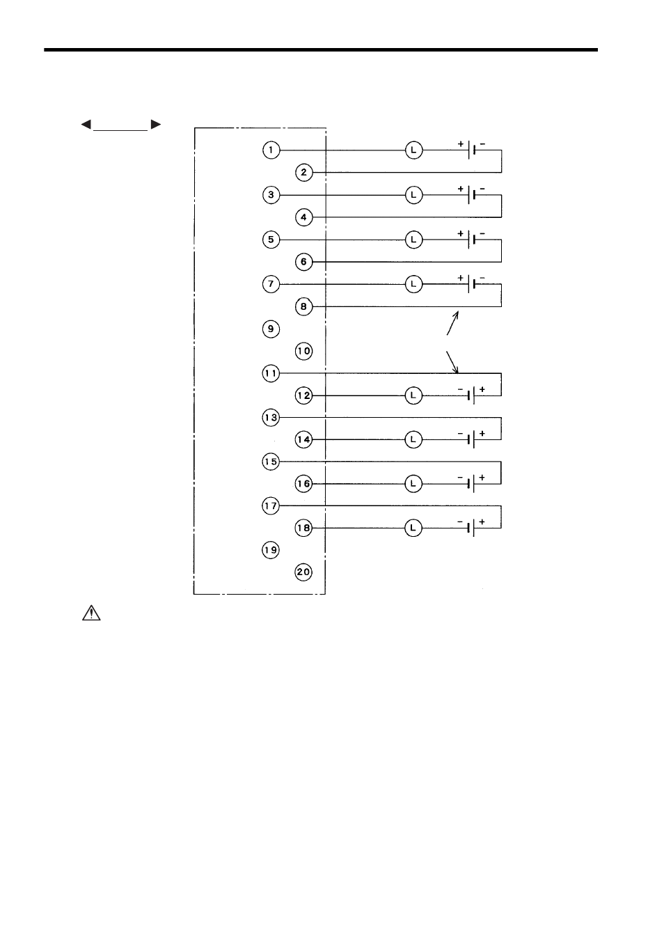
3) The following diagram shows an example of terminal connections.
If using a 12/24-VDC 8-point Output Module, connect a fuse, which complies with the
load specifications, in series with the load.
A protective fuse built into the following 12/24-VDC 8-point Output Modules
does not protect the output element. If a fuse is not connected, a fire or dam-
age to the devices or output circuits may occur if the load is short-circuited or
the circuit overloaded.
Note: (1) Crimp Terminals
Use M3 crimp terminals for the terminal block.
(2) Recommended Wires
Use wires of 0.8 mm
2
(AWG18) to 0.2 mm
2
(AWG24) to connect to the terminal
block.
(3) A blown-fuse detection circuit is not built into the circuit. If no output current
flows while the output signal indicator is lit under the rated voltage, the built-in
fuse may be blown. The built-in fuse must be replaced by a Yaskawa service
representative.
Loads
Loads
Output 1A
Output 1B
Output 2A
Output 2B
Output 3A
Output 3B
Output 4A
Output 4B
Not
connected
Not connected
Output 5A
Output 5B
Output 6A
Output 6B
Output 7A
Output 7B
Output 8A
Output 8B
Not connected
Sinking connection
Sourcing connection
12/24 VDC
12/24 VDC
12/24 VDC
12/24 VDC
12/24 VDC
12/24 VDC
12/24 VDC
12/24 VDC
Not
connected
EXAMPLE
CAUTION