3 installing i/o modules with connectors, 1) installing the module on the mounting base, Caution – Yaskawa 120 Series I/O Modules User Manual
Page 237
6 Installation and Wiring
6.1.3 Installing I/O Modules with Connectors
6-10
6.1.3
Installing I/O Modules with Connectors
This section describes the installation and removal procedures for the following I/O
Modules with connectors.
• 12/24 VDC 32-point I/O Modules
• 12/24 VDC 64-point I/O Modules
• Special Purpose Modules with Connectors
1) Installing the Module on the Mounting Base
Do not remove the connector covers from the Module connectors on the Mounting
Base slots where no Modules are installed.
The presence of any foreign matter in a Module connector may cause the
GL120 and GL130 to malfunction.
Make sure that all mounting screws for the Modules are securely tightened.
Loose screws may cause malfunction of the GL120 and GL130.
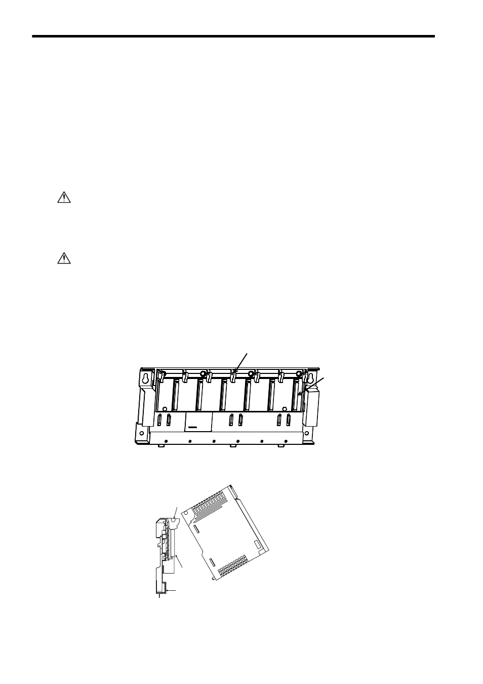
Install the Module with Connectors on the Mounting Base in the following manner.
a) Remove the cover from the module connector on the Mounting Base.
b) Install the Module on the Mounting Base as shown below.
(1) Hook the Module to the Module hook on the Mounting Base.
CAUTION
CAUTION
Module hook
Module connector
Mounting base
Module hook
Module
connector
DC24IN-32P