Caution – Yaskawa 120 Series I/O Modules User Manual
Page 76
3 Digital I/O Specifications
3.2.6 12/24-VDC 32-point Output Module
3-46
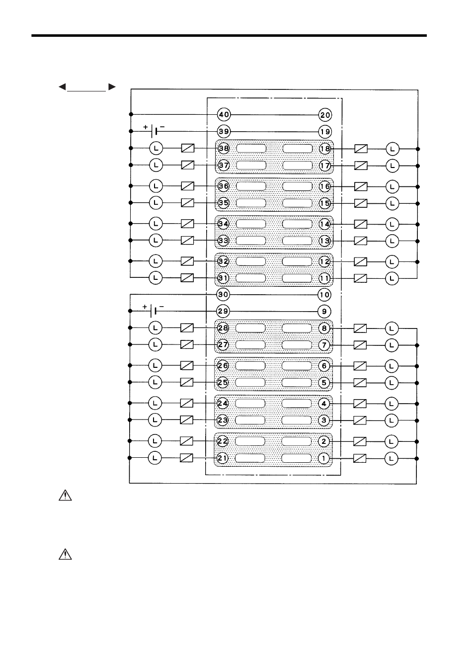
3) The following diagram shows an example of terminal connections.
Although a 0.3 A load can be connected to each output point of 12/24-VDC 32-point
Output Module, the total load must be 0.4 A or less for each of the four output points
shown in the shaded area. Keep the load distribution within the 0.4 A limit.
If this limit is exceeded, damage may occur to the output circuit.
If using a 12/24-VDC 32-point Output Module, connect a fuse, which complies with
the load specifications, in series with the load.
A protective fuse built into the following 12/24-VDC 32-point Output Modules
does not protect the output element. If a fuse is not connected, a fire or dam-
age to the devices or output circuits may occur if the load is short-circuited or
the circuit overloaded.
+ Common 2
- Common 2
Loads
Loads
Fuses
Fuses
Fuses
Fuses
Loads
Loads
+ Common 1
- Common 1
Output 32
Output 31
Output 30
Output 29
Output 28
Output 26
Output 24
Output 22
Output 20
Output 18
Output 16
Output 14
Output 12
Output 10
Output 8
Output 6
Output 4
Output 2
Output 15
Output 13
Output 11
Output 9
Output 7
Output 5
Output 3
Output 1
Output 27
Output 25
Output 23
Output 21
Output 19
Output 17
12/24 VDC
12/24 VDC
Pin No.
Pin No.
EXAMPLE
CAUTION
CAUTION