3 dc input modules, 1) connecting inductive loads, Caution – Yaskawa 120 Series I/O Modules User Manual
Page 267

6 Installation and Wiring
6.4.3 DC Input Modules
6-40
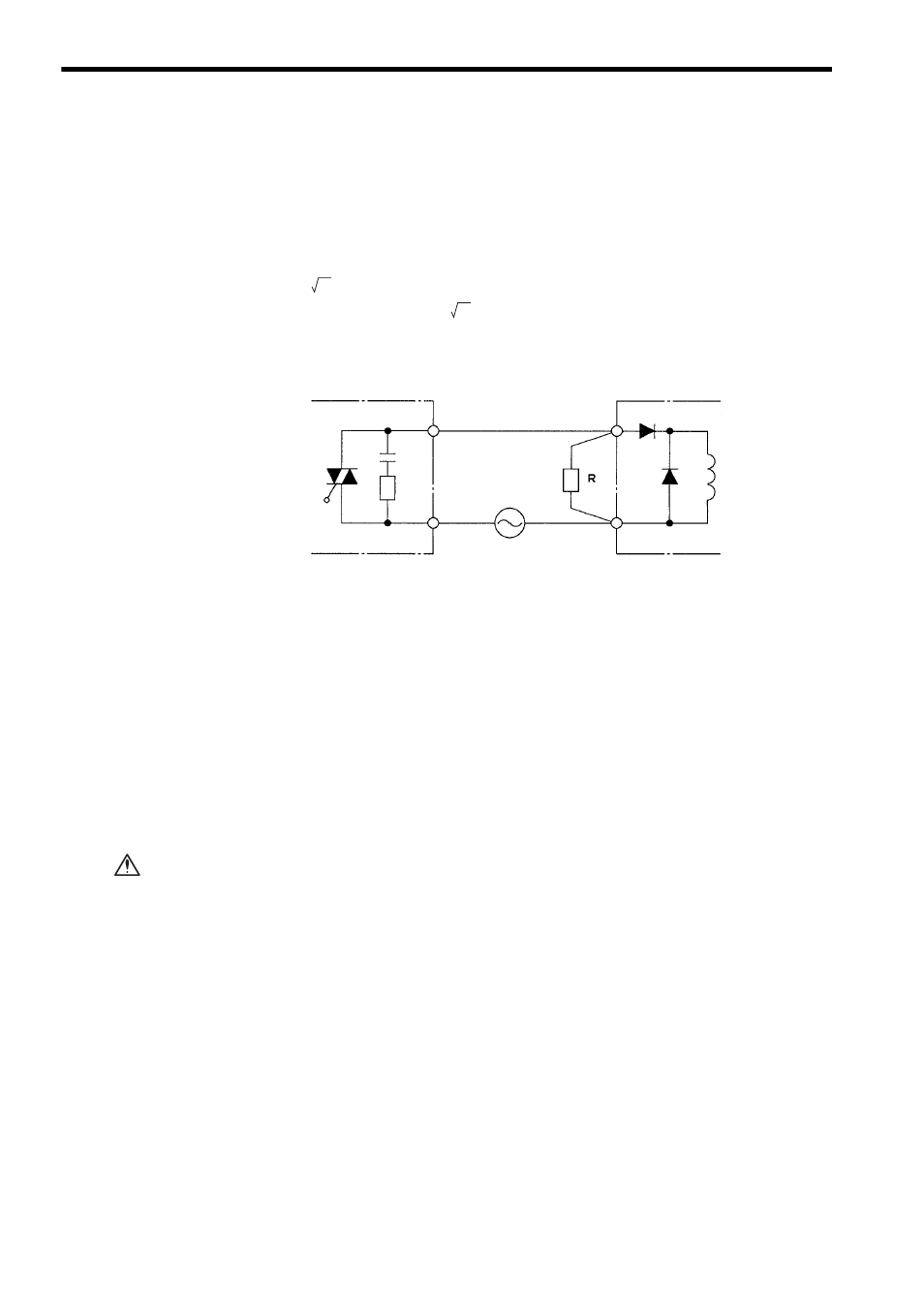
When the output of the AC Output Module is OFF, the rectifying diode is forward
biased and current A flows, as indicated by the dotted line in the figure, for a half the
cycle of the power supply to charge the capacitor. In the next half cycle, the rectify-
ing diode is reverse biased and blocks current A, so that discharge current B flows
from the capacitor. Here, the supply voltage and the voltage charge on the capacitor
are superimposed, and are applied to the solenoid. The peak value for this voltage is
about 2
E (E: supply voltage). This is why the rectifying diode requires to with-
stand a reverse voltage of 2
E or more.
Connect a resistance ranging from multiples of ten to several hundred k
Ω on both
ends of the solenoid to reduce the voltage applied to the solenoid.
Fig. 6.20 Solenoids with Diode (2)
b) The solenoid may not turn ON even though the output is ON.
When a solenoid with a diaode is connected, the solenoid may not turn ON because
the voltage at the output is not reduced to a usable operationg level due to the volt-
age charge on the capacitor. Here again, connect a resistance ranging from multi-
ples of ten to several hundred k
Ω on both ends of the solenoid to reduce the voltage
applied to the solenoid.
6.4.3
DC Input Modules
1) Connecting Inductive Loads
If connecting an inductive load in parallel with DC Input Module, connect the flywheel
diode in parallel with the inductive load to prevent surge voltage.
Failure to connect a flywheel diode may result in damage to the DC Input Mod-
ule.
Although the capacity of flywheel diode used must be adjusted to the load, the fol-
lowing diode is recommended for general applications:
• H14-series Diode (manufactured by Hitachi Ltd.) or equivalent
2
2
AC Output Module
Solenoid
Output
Rectifier diode
Flywheel
diode
Dummy
resistor
Common
Load power supply
(100/200 VAC)
CAUTION
