2 register output module i/o allocation screen – Yaskawa 120 Series I/O Modules User Manual
Page 216
5 Register I/O Specifications
5.4.2 Register Output Module I/O Allocation Screen
5-18
a) Service Scan (Normal/High-speed)
Set either Normal or High-speed scan for I/O processing.
b) Mode (8CH/16CH)
Select the number of data input from the Register Input Module.
Set either 8CH or 16CH.
c) Cycle
Select a cycle to read the input data. Each mode has six cycles.
d) Select Timing
If the cycle is set to “UESR SET,” the timing to read the input data can be selected.
5.4.2
Register Output Module I/O Allocation Screen
This section describes the MEMOSOFT I/O Allocation Screen and the Parameter
Setting Screen.
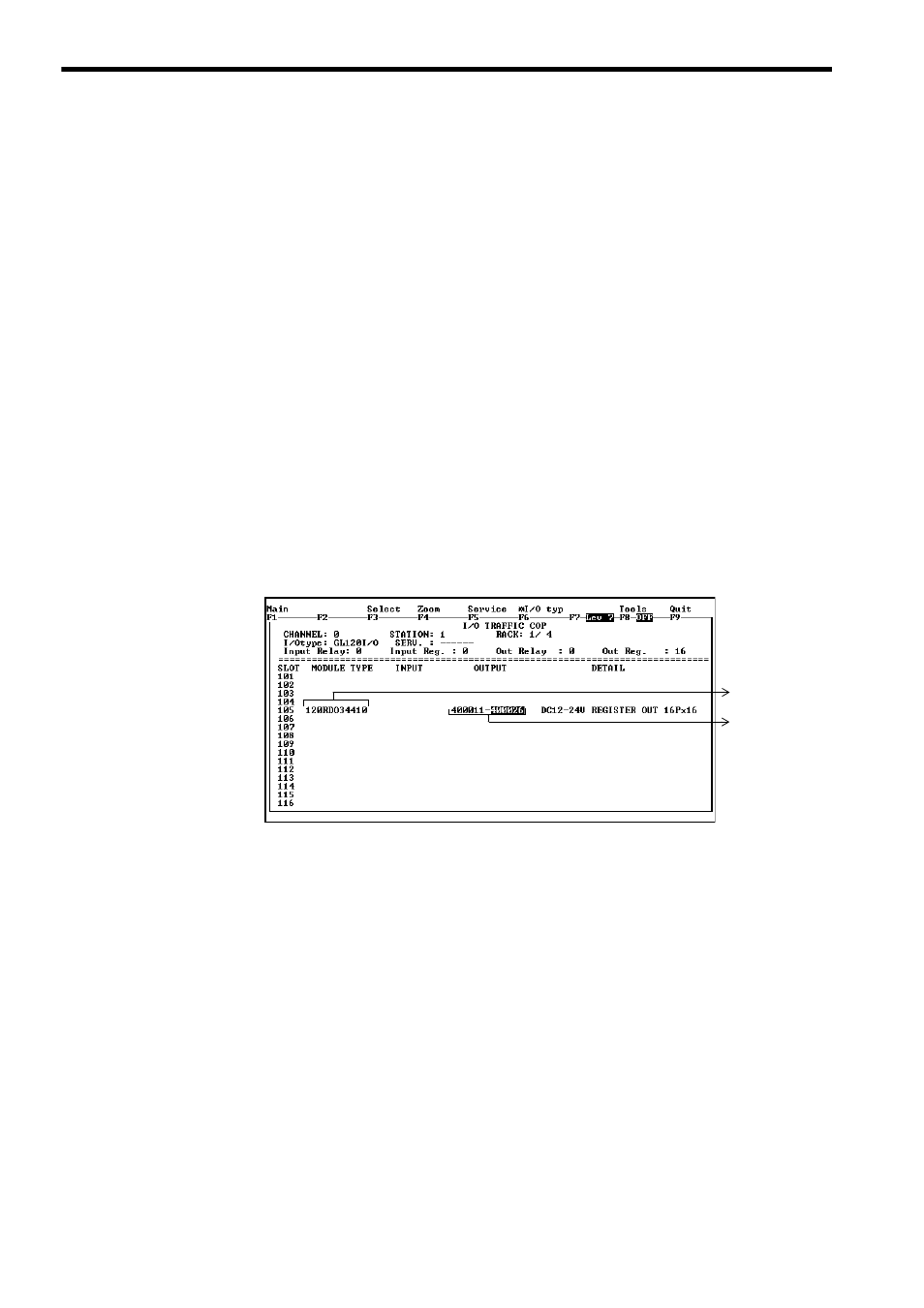
1) The I/O Traffic Cop (i. e., I/O Allocation) Screen
In this screen, set the following items.
Fig. 5.5 I/O Traffic Cop Screen
a) Module Type
Enter 120RDO34410 for the Register Output Module.
b) Set the I/O references to be used by the Register Output Module.
When the first reference number is input, the cursor will move to the field for the last
reference number and the last reference number will be displayed automatically,
indicating the reference number that can be input. Press Enter Key to accept the
value, or change it to the desired value, if necessary.
a)
b)