Yaskawa 120 Series I/O Modules User Manual
Page 158
4.1 Analog Input Specifications
4-11
4
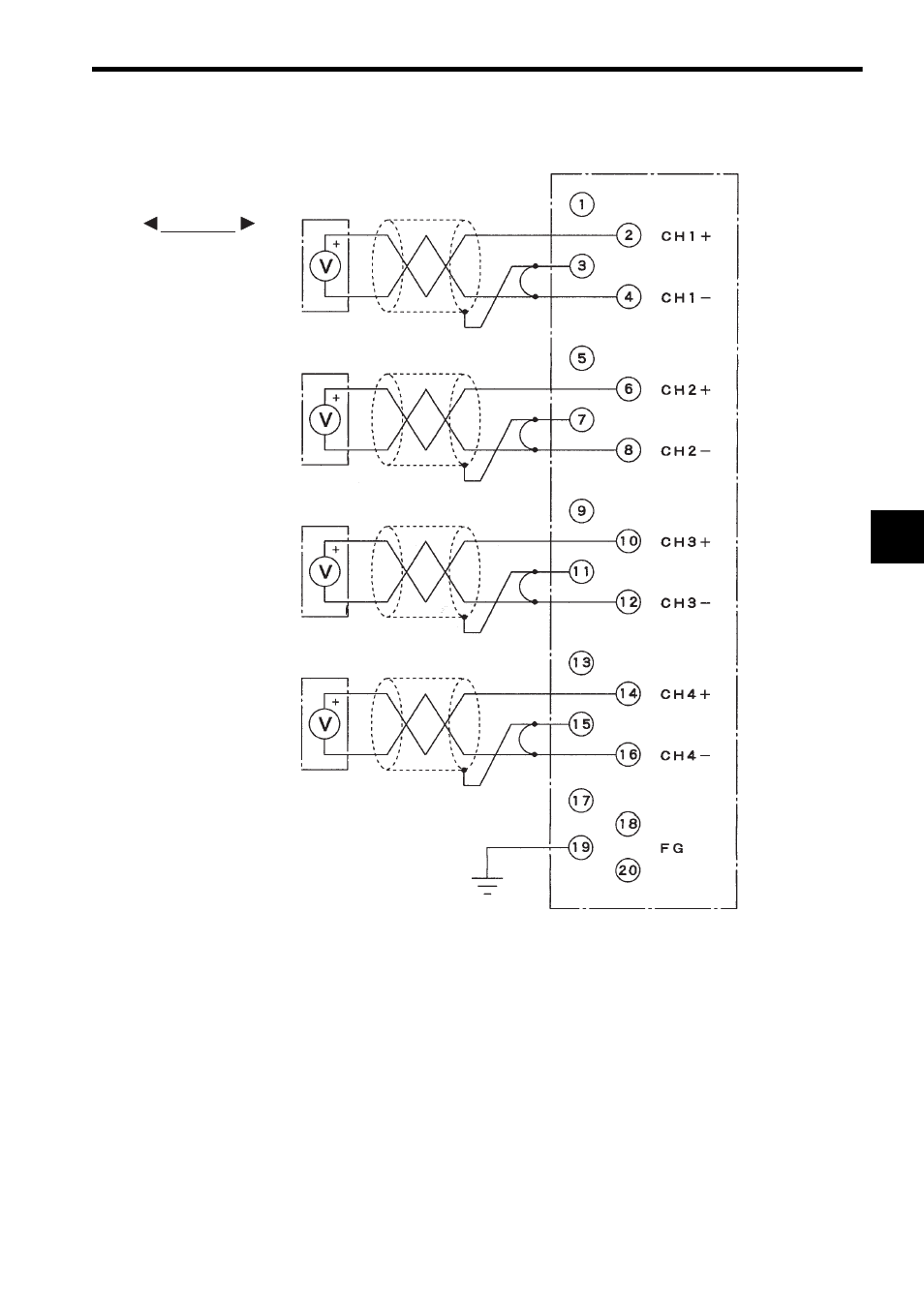
4) The following diagram shows an example of terminal connections.
Note: (1) Isolation between Input Channels
There is no isolation provided between the input circuit channels. If isolation
between channels is required, use a commercial isolation amplifier for each
channel.
(2) Recommended Wires
Use shielded twisted-pair wires of 1.3 mm
2
(AWG16) to 0.5 mm
2
(AWG20) to
connect to the terminal block.
(3) Connecting Single-ended Signal Sources
a) Connect + side of a single-ended signal to “+” terminal of the Module.
b) Connect - side of a single-ended signal to “-” terminal of the Module.
c) Connect the shield of a shielded twisted-pair wire to “Shield” terminal of the Module and short
“Shield” terminal to “V-” terminal. An incorrect connection will make input signal unstable and
cause malfunction.
External device Shielded twisted-pair wire
Not connected
Shield 1
External device
Not connected
Shield 2
External device
Not connected
Shield 3
External device
Not connected
Shield 4
Not connected
Not connected
Not connected
0 to 10 V
0 to 10 V
0 to 10 V
0 to 10 V
Shielded twisted-pair wire
Shielded twisted-pair wire
Shielded twisted-pair wire
Grounding resistance
100
Ω or max.
0
0
0
0
EXAMPLE