Caution, Example – Yaskawa 120 Series I/O Modules User Manual
Page 82
3 Digital I/O Specifications
3.2.7 12/24-VDC 64-point Output Module
3-52
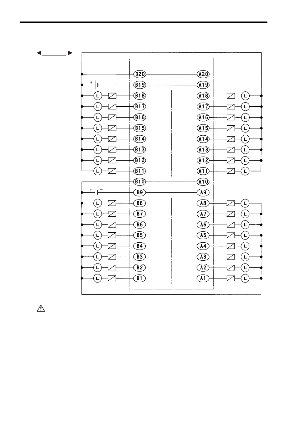
3) The following diagram shows an example of terminal connections.
If using a 12/24-VDC 64-point Output Module, connect a fuse, which complies with
the load specifications, in series with the load.
A protective fuse built into the following 12/24-VDC 64-point Output Modules
does not protect the output element. If a fuse is not connected, a fire or dam-
age to the devices or output circuits may occur if the load is short-circuited or
the circuit overloaded.
Note: (1) CN1 pins A9 and B9, pins A10 and B10, pins A19 and B19, and pins A20 and
B20 are internally connected. Connect these pins externally as well. Not con-
necting them can cause malfunction.
(2) Connector for External Connections (included)
Connector: FCN-361J040-AU (soldered) (manufactured by Fujitsu Ltd.)
Cover: FCN-360C040-B (manufactured by Fujitsu Ltd.)
(3) Recommended Wires
Use wires of 0.26 mm
2
(AWG23) to connect to each connector pin.
Loads
Loads
Output 32
Output 30
Output 28
Output 26
Output 24
Output 22
Output 20
Output 18
+ Common 2
12/24 VDC
Loads
- Common 2
+ Common 1
- Common 1
Output 16
Output 14
Output 12
Output 10
Output 8
Output 6
Output 4
Output 2
Output 31
Output 29
Output 27
Output 25
Output 23
Output 21
Output 19
Output 17
+ Common 2
- Common 2
+ Common 1
- Common 1
Output 15
Output 13
Output 11
Output 9
Output 7
Output 5
Output 3
Output 1
Loads
Fuses
Fuses
Fuses
Fuses
(Continued on next page)
CN1 connector
pin numbers
CN1 connector
pin numbers
12/24 VDC
EXAMPLE
CAUTION