7 installing the theft protection, Installing the theft protection – SMA SSM16-11 User Manual
Page 42
6 Electrical Connection
SMA Solar Technology AG
42
SSM16-24-IA-IEN105120
Installation Guide
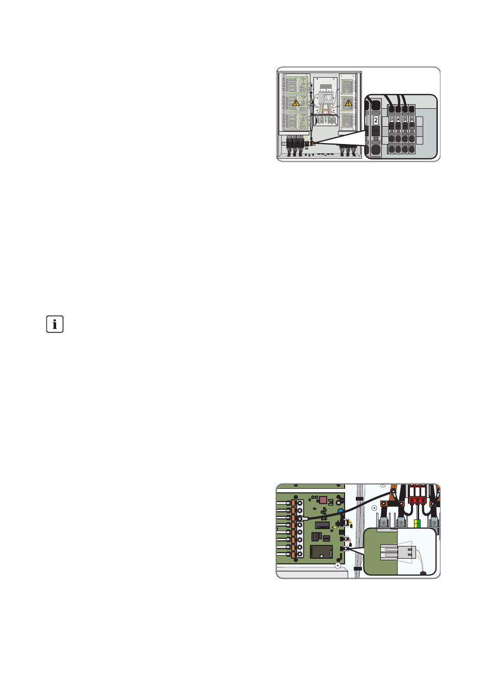
4. Connect the connection cable to the terminal strip as
shown in the circuit diagram.
5. Tighten the cable gland.
6.7 Installing the Theft Protection
On the Sunny Central 100/200/250/350 inverters and the Sunny Central inverters in the HE‑11
series you can activate the theft protection for the PV modules via the Sunny String-Monitor.
The contacts at the PV modules are connected to form a signal chain for the theft protection. Upon
interruption of the signal chain, an theft warning appears in the Sunny Central Control display, and
an e-mail message is sent immediately.
Installation of the cable gland and wiring is carried out by the customer.
Requirement:
☐ The signal chain has a maximum 300 Ohm loop resistor.
1. Implement the contacts at the PV modules as normally closed contacts and connect to form a
signal chain.
2. Integrate the signaling contact for the theft
protection on the String Monitor Unit into the
monitoring circuit.
3. Activate the theft protection via the Sunny Central Control or via Sunny Data Control (see
section 9.3.7 ”Setting the Theft Protection”, page 52 or section 10.3.8 ”Setting the Theft
Protection”, page 59)
Nighttime deactivation
The theft protection only functions if the nighttime deactivation has been deactivated. If the
nighttime deactivation is activated, the message is not sent until the supply voltage has been
switched on again.
• Deactivate the nighttime deactivation for theft protection (see section 9.3.6 ”Setting the