4 connecting the grounding cable, Connecting the grounding cable – SMA SSM16-11 User Manual
Page 35
SMA Solar Technology AG
6 Electrical Connection
Installation Guide
SSM16-24-IA-IEN105120
35
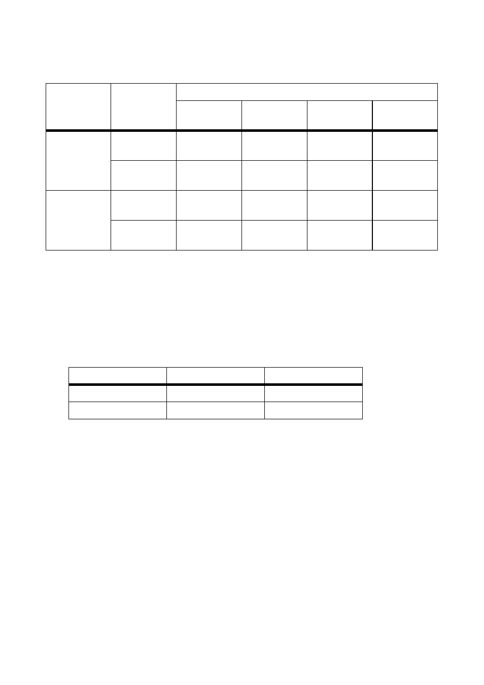
Terminal Cross Section of Aluminum Cable
1. Remove filler-plugs from the cable glands.
2. Guide the DC main cable through the cable glands into the enclosure interior. Make sure
polarity is correct when doing this.
3. Strip the main DC cable appropriately for terminal used and attach it to cage clamps. Tighten
to the torque specified.
4. Make sure that it is securely in place.
5. Tighten the cable glands.
6.4 Connecting the Grounding Cable
To guarantee the functionality of the integrated surge arrester, this must be connected to an external
earth.
Requirement:
☐ Minimum cross section of the grounding cable 16 mm
2
1. Remove the filler-plugs from the cable gland.
2. Guide the grounding cable through the cable gland into the enclosure interior.
3. Strip the grounding cable 16 mm.
4. Connect the grounding cable to the ground terminal (torque: 3.5 Nm).
5. Tighten the cable gland.
Connection
terminal
Number of
cables
Terminal cross section
Round,
single-strand
Round,
multi-strand
Sectoral,
single-strand
Sectoral,
multi-strand
maximum
240 mm
2
1
*
*
Sunny String-Monitor SSM16/24-11 with bottom plate: connection of 1 cable per DC terminal possible.
25 mm
2
…
50 mm
2
25 mm
2
…
240 mm
2
50 mm
2
…
185 mm
2
95 mm
2
…
185 mm
2
2
**
**
Sunny String‑Monitor SSM16/24-11 without bottom plate: connection of 2 cables per DC terminal possible.
25 mm
2
…
50 mm
2
25 mm
2
…
120 mm
2
50 mm
2
…
120 mm
2
50 mm
2
…
95 mm
2
maximum
300 mm
2
1
-
150 mm
2
…
300 mm
2
150 mm
2
…
185 mm
2
150 mm
2
…
240 mm
2
70 mm
2
70 mm
2
…
185 mm
2
95 mm
2
…
185 mm
2
95 mm
2
…
185 mm
2
Terminal
Stripped insulation
Torque
240 mm² terminal
35 mm
40 Nm
300 mm² terminal
45 mm
50 Nm