Grass Valley UniConfi NVISION Series v.2.1 User Manual
Page 49
37
UniConfig
User’s Guide
slave frames. (The master frame is also the frame that communicates with the router control
system.)
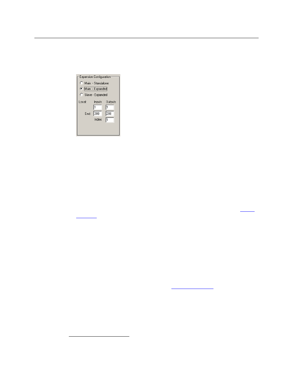
When you click ‘Main - Expanded‘, additional fields appear in the ‘Expansion Configuration’
section:
Fig. 6-6: Expansion Section (Sample, NV8288-Plus)
The expansion section identifies the range of physical inputs and outputs for the particular
frame in the expanded router. The ‘Index’ value identifies the frame in the expanded router.
In the case of an NV7512-Plus audio router having 4 frames for a 2048 × 2048 (stereo) switch-
ing matrix,
1
the ranges for the frames are
Frame
Index
Input Range
Output Range
Main 1
1–2048
1–512
Slave 2
1–2048
513–1024
Slave 3
1–2048
1025–1536
Slave 4
1–2048
1537–2048
Other routers require different values in the ‘Expansion Configuration’ section. See
5 Enter a number in the ‘Index’ field provided in the ‘Expansion’ section. The frames in the
expanded router must have unique indexes. It is a good idea to specify 1 for the main frame.
6 Enter the range of inputs and outputs for the frame.
7 Enter partition data. As mentioned, these data are dependent on your system requirements
and cannot be addressed here.
Reminder: the partition numbers must be unique.
Choose the signal type according to the input signal format for the partition. The signal type,
in conjunction with the switch point setup, determines the rules used by the router for
switching the signals when the operator executes a “take.”
For information on setting the switch point, see
8 Click Write All to write changes to the control card.
9 Repeat steps 1 through 8 for the secondary control card on the master router (if it exists).
1. This is equivalent to a 4096 × 4096 mono matrix.