Grass Valley UniConfi NVISION Series v.2.1 User Manual
Page 153
141
UniConfig
User’s Guide
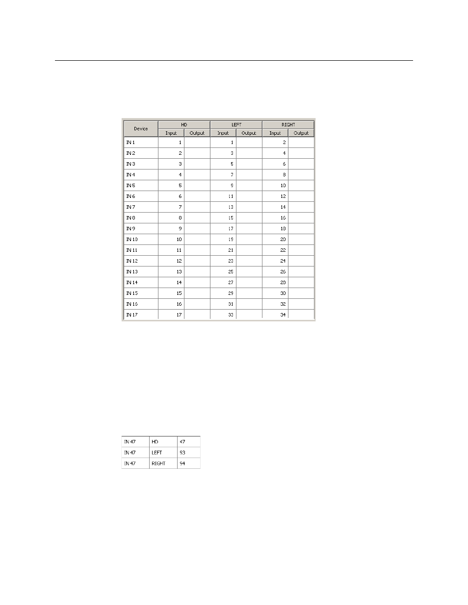
For stereo, the “left” inputs will start at 1 and the “right” inputs will start at 2. Both levels
increment by 2 (because each connector provides 2 mono inputs).
Complete the settings in this page and click ‘Next’ at the bottom of the window. The third
and final window appears, in which is displayed a table of the devices that will be created:
The table shows the ports for each of the virtual levels for each device. Note that each of the
mono levels increments by 2 and that the mono levels are paired for each device (1,2), (3,4),
(5,6) and so on.
If the proposed result appearing in this window is correct, click ‘Finish’. Otherwise, amend or
cancel your entries.
Perform the same 3-step process for stereo outputs. When you process the second step,
ignore the input columns and assign starting and increment values for the outputs.
5 When you complete both input and output device sets, you can examine NV9000-SE Utili-
ties’ various tables to verify your work. This is an excerpt from the ‘PhysConns’ table showing
input 55:
This table fragment shows that the stereo input (IN 47) has two mono levels that come from
ports 93 and 94 as expected and fit the formulas given earlier:
R = S × 2
L = R –
1
(The device names for both level sets should be similar so that operators can choose the right
device without thinking.)
The NV9000 configuration used in this example is somewhat contrived and simplistic, but it
illustrates the method. It is easy to create variations of the method.