Using the monitor level – Grass Valley UniConfi NVISION Series v.2.1 User Manual
Page 115
103
UniConfig
User’s Guide
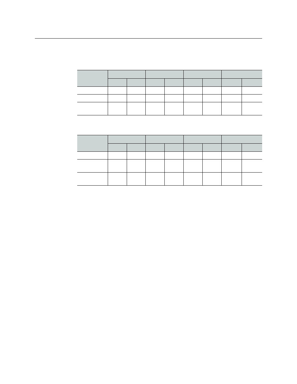
5 Enter values for inputs and outputs for the level in the following fields.
For control cards having application version 13.0.3.xx and earlier, enter values selected from
this table:
For control cards having application version 14.0.0.xx and later, enter values selected from
this table
Note that controller ‘End’ values for input and output are derived. You cannot enter
values in these fields (which are grayed out).
6 From the ‘Signal Type’ drop-down list, select the signal type ‘Monitor’.
7 Click Write All to writes changes to the control card.
8 Repeat steps 1–7 for each control card in the router.
Using the Monitor Level
The control panel operator can switch signals to monitoring equipment if the router control
system defines a monitor level that corresponds to the monitor level, in the router, that was
defined in UniConfig.
Third-party control systems or software drivers can be used to control the monitoring of router
inputs and outputs.
The ability to monitor NV8500 router inputs assumes that the control card in the router is
running application version 14.0.0.xx and later (matching FPGA versions: CPLD, SV0900-07,
SV0901-06 and newer).
Router
Physical Input
Controller Input
Physical Output
Controller Output
Start
End
Start
End
Start
End
Start
End
NV8144
1
144
1
144
1
2
1
2
NV8280
1
576
1
576
1
2
1
2
NV8576,
NV8576-Plus
1
1152
1
1152
1
2
1
2
Router
Physical Input
Controller Input
Physical Output
Controller Output
Start
End
Start
End
Start
End
Start
End
NV8144
1
144
1
144
1
4
1
4
NV8280/
NV8280-Plus
1
576
1
576
1
4
1
4
NV8576/
NV8576-Plus
1
1152
1
1152
1
4
1
4