Connectors, Mono and stereo configuration methods, Method 1 – Grass Valley UniConfi NVISION Series v.2.1 User Manual
Page 144: Connectors mono and stereo configuration methods, Method 1 details

132
Technical Details
Technical Details
Connectors
The following table shows the pinout for the DE9 connectors (RS-232) at the front of EM0374
control cards:
The same pinout applies to the DE9 connectors (RS-232) at the rear of the NV8288 and NV8288-
Plus router (which use EM0529 control cards).
Mono and Stereo Configuration Methods
These methods are for NV9000 systems. We cannot address third-party router control systems.
Method 1
Problem: how do you configure an input or output to be both stereo and mono?
In UniConfig, create 2 overlapping partitions: one for stereo and one for mono. (The stereo parti-
tion and the mono partition use the same physical ports.)
In the NV9000 configuration, create two sets of devices, one for use as stereo, and one or use as
mono. Both sets of devices refer to the same ports, but in a different way.
Method 1 Details
In UniConfig
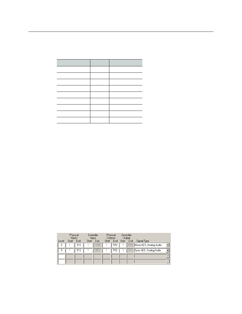
Create 2 overlapping partitions, one for stereo and one for mono. This is an example for the
NV7512:
Here we have 512 connectors supporting 512 stereo signals or 1024 mono channels. Here we
chose levels 2 and 3 because, in the NV9000 system of this example, level 1 is for the HD router.
PC End
Pin
Router End
DCD
1
Ground
RXD
2
TXD
TXD
3
RXD
DTR
4
DSR
Signal Ground
5
Signal Ground
DSR
6
DTR
RTS
7
CTS
CTS
8
RTS
Ground
9
Ground
