Reference indicator, Internal indicators, Disk module indicators – Grass Valley K2 Summit Client Service Manual Nov.23 2009 User Manual
Page 39
12 October 2009
K2 Summit Production Client Service Manual
39
Internal indicators
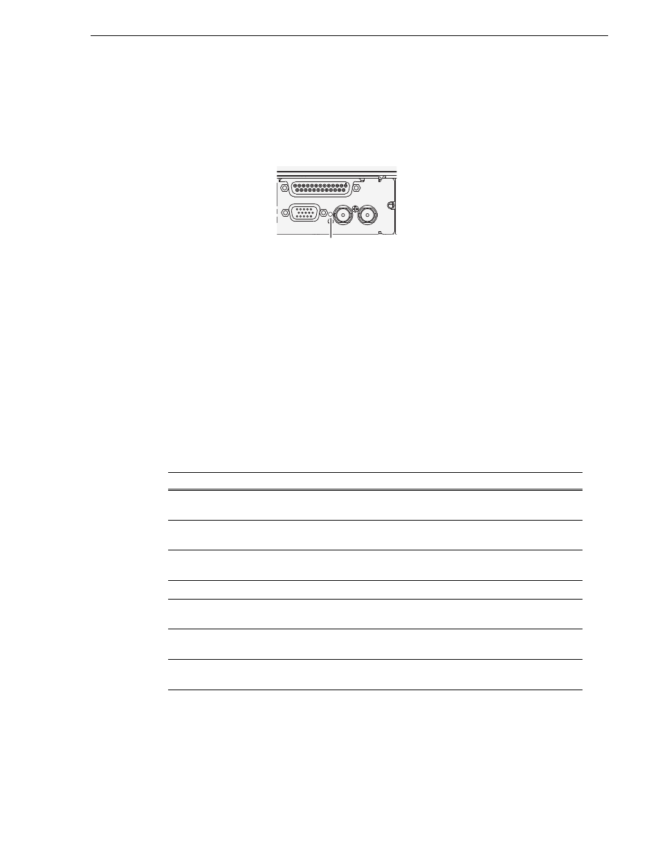
Reference indicator
There is a small hole in the carrier module next to the “REF. LOOP THROUGH”
BNC connectors.
Through this hole a LED is visible. When the LED is lit, the reference signal is present
and locked.
Internal indicators
You must remove one or more modules to expose the following indicators for
viewing.
Disk module indicators
You must remove the front bezel assembly to see these LEDs. Each disk module has
LEDs that indicate status. The LEDs are located on the disk backplane. Flexible light
pipes transmit the light so that it appears on the disk pillar next to the disk module.
The following table explains the status conditions indicated by the different LED
behaviors. If two or more status conditions occur simultaneously, the LED displays
the behavior for the highest priority condition. Priority number 1 is the highest priority
LED behavior
Status Condition
Priority
Amber flashing pattern.
Identify — The drive is being directed to identify itself
by Storage Utility or some other application.
1
Green flashing pattern twice a
second.
Rebuild — The RAID controller has marked the drive
as rebuilding.
3
Red ON solid.
Fault — The RAID controller has marked the drive as
faulty.
3
Amber ON solid.
Offline — The drive is unbound.
3
Green flashing pattern ten times a
second.
Normal drive activity — The drive is healthy and disk
access is underway.
3
Green ON solid
Normal drive activity — The drive is healthy and no
disk access is currently underway.
3
OFF
No drive — Drive is not present or is not fully engaged
in slot.
—
GPI
VGA
REF. LOOP THROUGH
Reference