Section 3, Switch configuration, Figure 19. configuration switches – Grass Valley 3-CCD CameraMan User Manual
Page 23
CameraMan Installation and Operation Manual
23
Section
3
Switch Configuration
Once connected to the power supply and control devices, the DIGITAL
Camera must be configured to work in the desired application. To begin,
remove the configuration plate on the back right side of the camera by
removing the two screws holding it in place. Behind it are the configuration
switches (
).
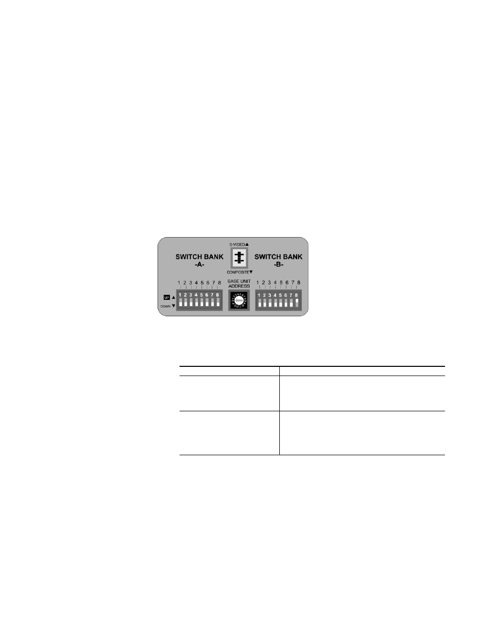
Figure 19. Configuration Switches
Note
All switches not discussed in this section should remain in the DOWN or OFF
position.
Switch Bank A
Dip Switch 7 (Baud Rate)
Used to configure camera Baud Rate for the RS-
232 and RS-485 ports. Set the switch in the UP
position for 19,200 baud and the DOWN position
for 9600 baud. (The factory default is UP.)
Dip Switch 8 (Memory)
For the majority of applications, this switch should
be set to the UP (UNLOCK) position. When in the
DOWN (LOCK) position, all programmed features
are locked and cannot be overridden. (The
factory default is UP.)