Tally light interface port, Figure 13. tally light interface port – Grass Valley 3-CCD CameraMan User Manual
Page 16
16
CameraMan Installation and Operation Manual
Section 1 — General
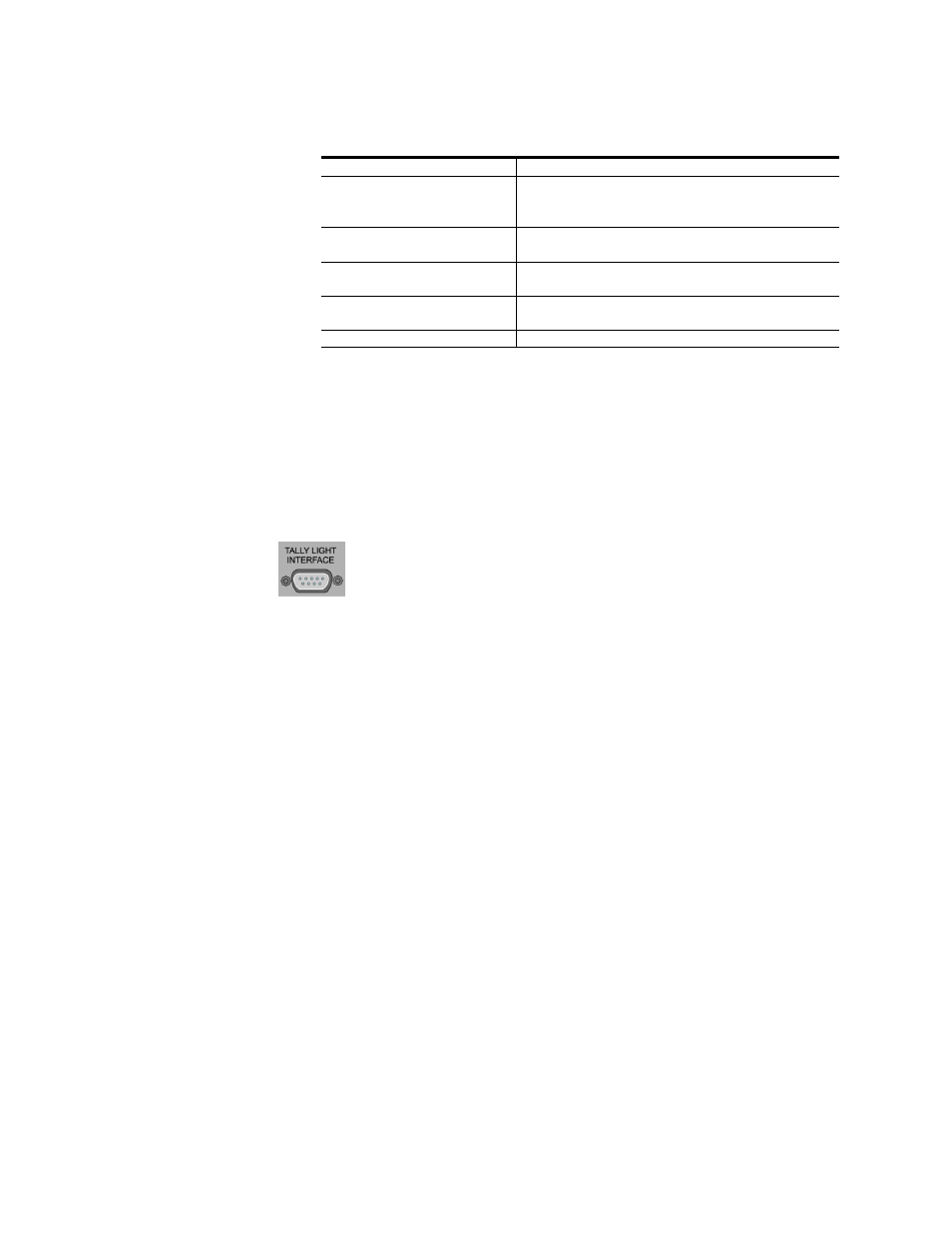
Tally Light Interface Port
The Tally Light Interface Port (
) provides output and external
control for CameraMan Tally Light.
Figure 13. Tally Light Interface Port
Switch Bank B
Switch 1 (Protocol Select
Switch)
Used to select the type of Protocol being used for
RS-232 and RS-485 communications. This can
be configured as either Basic or High Reliability.
Switch 4 (RF Commands
Switch)
Used to enable or disable the RF Receiver in the
CameraMan camera.
Switch 5 (Preset Save)
Used to determine how the preset settings will be
saved.
Switch 8 (Interlink Switch)
Used to disable commands from being sent on
the RS-485 bus to other CameraMan devices.
Switches 2, 3, 6 and 7
Reserved for future use.
See also other documents in the category Grass Valley Equipment:
- LDK 5302 (24 pages)
- SFP Optical Converters (18 pages)
- 2000GEN (22 pages)
- 2011RDA (28 pages)
- 2010RDA-16 (28 pages)
- 2000NET v3.2.2 (72 pages)
- 2000NET v3.1 (68 pages)
- 2020DAC D-To-A (30 pages)
- 2000NET v4.0.0 (92 pages)
- 2020ADC A-To-D (32 pages)
- 2030RDA (36 pages)
- 2031RDA-SM (38 pages)
- 2041EDA (20 pages)
- 2040RDA (24 pages)
- 2041RDA (24 pages)
- 2042EDA (26 pages)
- 2090MDC (30 pages)
- 2040RDA-FR (52 pages)
- LDK 4021 (22 pages)
- 3DX-3901 (38 pages)
- LDK 4420 (82 pages)
- LDK 5307 (40 pages)
- Maestro Master Control Installation v.1.5.1 (455 pages)
- Maestro Master Control Installation v.1.5.1 (428 pages)
- 7600REF Installation (16 pages)
- 7600REF (84 pages)
- 8900FSS (18 pages)
- 8900GEN-SM (50 pages)
- 8900NET v.4.3.0 (108 pages)
- Safety Summary (17 pages)
- 8900NET v.4.0.0 (94 pages)
- 8906 (34 pages)
- 8911 (16 pages)
- 8900NET v.3.2.2 (78 pages)
- 8914 (18 pages)
- 8912RDA-D (20 pages)
- 8916 (26 pages)
- 8910ADA-SR (58 pages)
- 8920ADC v.2.0 (28 pages)
- 8920ADC v.2.0.1A (40 pages)
- 8920DAC (28 pages)
- 8920DMX (30 pages)
- 8920ADT (36 pages)
- 8920MUX (50 pages)
- 8921ADT (58 pages)