Cameraman configuration panel, Figure 12. configuration panel – Grass Valley 3-CCD CameraMan User Manual
Page 15
CameraMan Installation and Operation Manual
15
CameraMan Configuration Panel
•
Indicates that the camera has acquired the RF signal from the TRP and is
receiving valid data. When this LED is OFF, TRP power is usually OFF.
•
Reserved for future use.
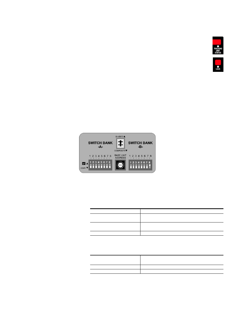
CameraMan Configuration Panel
Behind the configuration plate on the lower right side rear of the 3-CCD
DIGITAL Camera is the configuration panel (). These DIP and rotary
switches are used to link the camera’s settings to other components in the
system.
Figure 12. Configuration Panel
Note
After changing any switch’s settings, turn the camera off, then back on to
activate the change.
Switch Bank A
Switch 7 (Baud Rate
Switch)
Used to change the camera’s Baud Rate.
Switch 8 (Memory Lock
Select Switch)
Can be used to prevent programmed settings
from being accidentally overridden.
Switches 1, 2, 3, 4, 5 and 6
Reserved for future use.
Center Control
Switches
Video Select Switch
Non-functional
Base Unit Address
Used to configure the address of the Camera.