Connecting the camera system, Connecting camera control cables, Figure 15. back of camera block – Grass Valley 3-CCD CameraMan User Manual
Page 18: Connecting the sdi video output, Connecting to the rs-232 port
18
CameraMan Installation and Operation Manual
Section 2 — Mounting the Camera
Connecting the Camera System
Follow the instructions below to begin connecting the camera to the
system.
Note
After connecting each cable to the camera, let it hang loosely behind the
camera. Then follow the instructions in
before
attaching the other ends of the cable to other equipment. This relieves undue
stress on the cables and allows the camera to move freely.
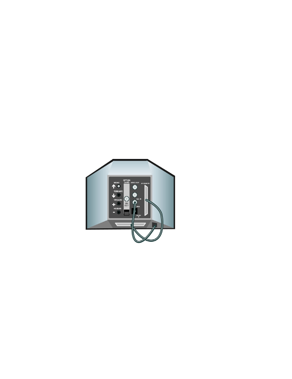
Connecting Camera Control Cables
•
On the back of the camera block (
), there are two cables. These
provide the camera lens, power, and video signals. The cables must be
attached for the camera to operate properly.
•
Connect the 12-pin connector to the IRIS jack.
•
Connect the 50-pin SCSI connector to the I/F REMOTE jack.
Figure 15. Back of Camera Block
Connecting the SDI Video Output
The 3-CCD DIGITAL Camera supports SDI format (270 Mbls component
out).
Connect to the BNC jack labeled SDI OUT on the back of the camera
shroud, using a standard SDI coaxial cable with a BNC connector.
Connecting to the RS-232 Port
The 3-CCD DIGITAL Camera provides for RS-232 communications using
the DB-9 jack on the back of the camera, labeled RS-232. This RS-232 port
can be used to control the CameraMan Camera from external devices such
as a PC or other vendor control system (i.e.: AMX, Crestron). Connect to