Cameraman led displays, Figure 11. cameraman leds – Grass Valley 3-CCD CameraMan User Manual
Page 14
14
CameraMan Installation and Operation Manual
Section 1 — General
•
Power input for the CameraMan Camera. Plug only a Grass Valley power
supply (supplied) into this jack. No other types of power supplies should be
used.
•
Used to power on/off the CameraMan Camera.
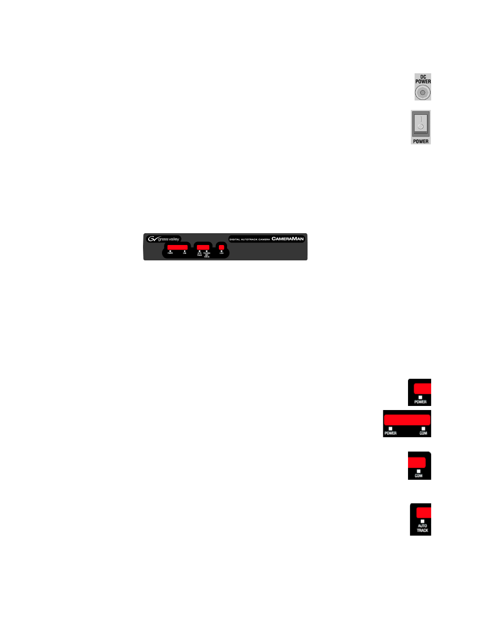
CameraMan LED Displays
On the front of the CameraMan CPT 2018 3-CCD Camera, there are several
LEDs (
). These indicate various functions that are being per-
formed by the camera.
Figure 11. CameraMan LEDs
When the camera is first powered ON, all LEDs will illuminate. During this
time, basic system hardware checks are being performed. These checks
include communication with the camera interface board which verifies
proper installation of the camera block on the pan/tilt unit. After the initial
system checks are completed, the LEDs will turn on and off one by one in
a binary pattern. This pattern represents the progress the camera is making
during hardware initialization. During this initialization, pan/tilt positions
and camera settings are being restored. Once initialization is complete, the
camera LEDs will represent the following functions:
•
Indicates that the camera has an active power supply and is powered ON.
•
(Between the Power and COM LEDs) The camera is in the camera
setup mode.
•
Indicates that the camera is receiving valid network data on a communication
link (the LEDs on the back of the camera only indicate line activity, not valid
data).
•
Indicates that the camera is in autoTRACK mode. The IR spinners are running
and the camera is attempting to acquire data from the TRP.