Camera control block overview, Figure 10. camera control block – Grass Valley 3-CCD CameraMan User Manual
Page 13
CameraMan Installation and Operation Manual
13
CameraMan Ports and Jacks
•
Allows communication with the pan/tilt unit.
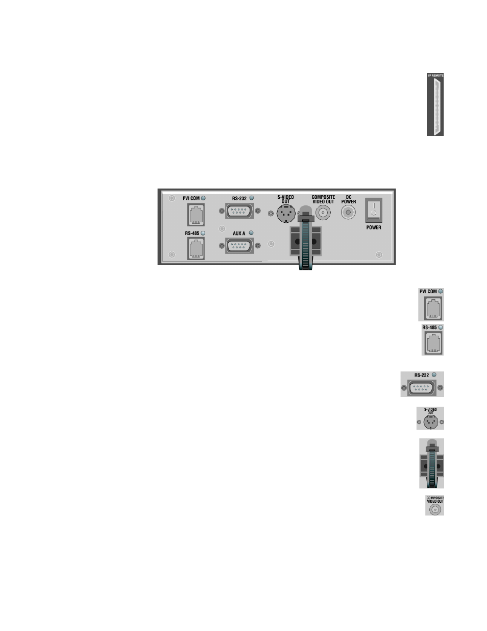
Camera Control Block Overview
Interface connections are located on the back of the camera control block
(
Figure 10. Camera Control Block
•
Used by certain Grass Valley devices as a communication interface to the
camera system. (For example, a hard-wired keypad would attach here). This
is a standard 6-conductor RJ-11 jack.
•
Used for RS-485 communications between the camera system and other
Grass Valley devices. This jack can be used to network multiple cameras or to
connect appropriate Grass Valley approved peripherals using a Grass Valley
T-connector. This is a standard 4-position modular handset jack.
•
Provides RS-232 communications to external devices such as PC’s or
other vendor control systems. This connector is a standard DB-9
(female) connector.
•
Non-functional
•
Helps keep cables from becoming disconnected, or hindering the pan and
tilt capabilities of the camera.
•
Non-functional