Configuration procedure – H3C Technologies H3C SecPath F1000-E User Manual
Page 26
25
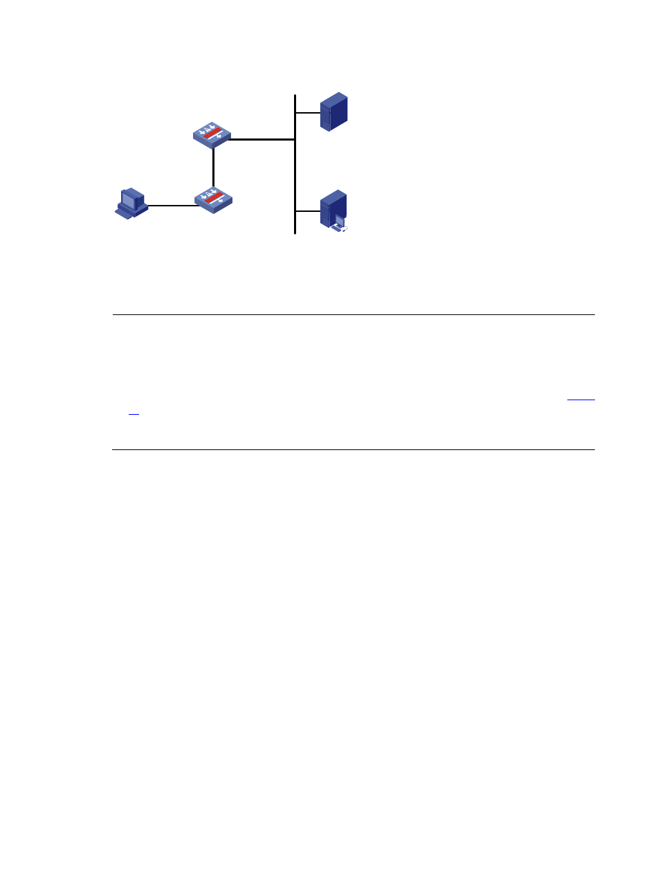
Figure 11 Configure Layer 3 portal authentication
Device A
Host
8.8.8.2/24
GE0/2
20.20.20.1/24
Portal server
192.168.0.111/24
RADIUS server
192.168.0.112/24
GE0/1
192.168.0.100/24
Device B
GE0/2
8.8.8.1/24
GE0/1
20.20.20.2/24
Configuration procedure
NOTE:
•
Make sure that the IP address of the portal device added on the portal server is the IP address of the
interface connecting users (20.20.20.1 in this example), and the IP address group associated with the
portal device is the network segment where the users reside (8.8.8.0/24 in this example).
•
You need to configure IP addresses for the host, Device A, Device B, and the servers as shown in
and ensure that they can reach each other.
•
Perform configurations on the RADIUS server to ensure that the user authentication and accounting
functions can work normally.
Perform the following configuration on Device A:
Step1
Configure a RADIUS scheme
# Create a RADIUS scheme named rs1 and enter its view.
[DeviceA] radius scheme rs1
# Set the server type for the RADIUS scheme. When using the CAMS or iMC server, you need to set the
server type to extended.
[DeviceA-radius-rs1] server-type extended
# Specify the primary authentication server and primary accounting server, and configure the keys for
communication with the servers.
[DeviceA-radius-rs1] primary authentication 192.168.0.112
[DeviceA-radius-rs1] primary accounting 192.168.0.112
[DeviceA-radius-rs1] key authentication radius
[DeviceA-radius-rs1] key accounting radius
# Specify that the ISP domain name should not be included in the username sent to the RADIUS server.
[DeviceA-radius-rs1] user-name-format without-domain
[DeviceA-radius-rs1] quit
Step2
Configure an authentication domain
# Create an ISP domain named dm1 and enter its view.
[DeviceA] domain dm1