Configuration procedure – H3C Technologies H3C MSR 50 User Manual
Page 58
•
Router C operates in broadcast server mode and sends broadcast messages from Ethernet 1/1.
•
Router B and Router A operate in broadcast client mode and receive broadcast messages through
their respective Ethernet 1/1.
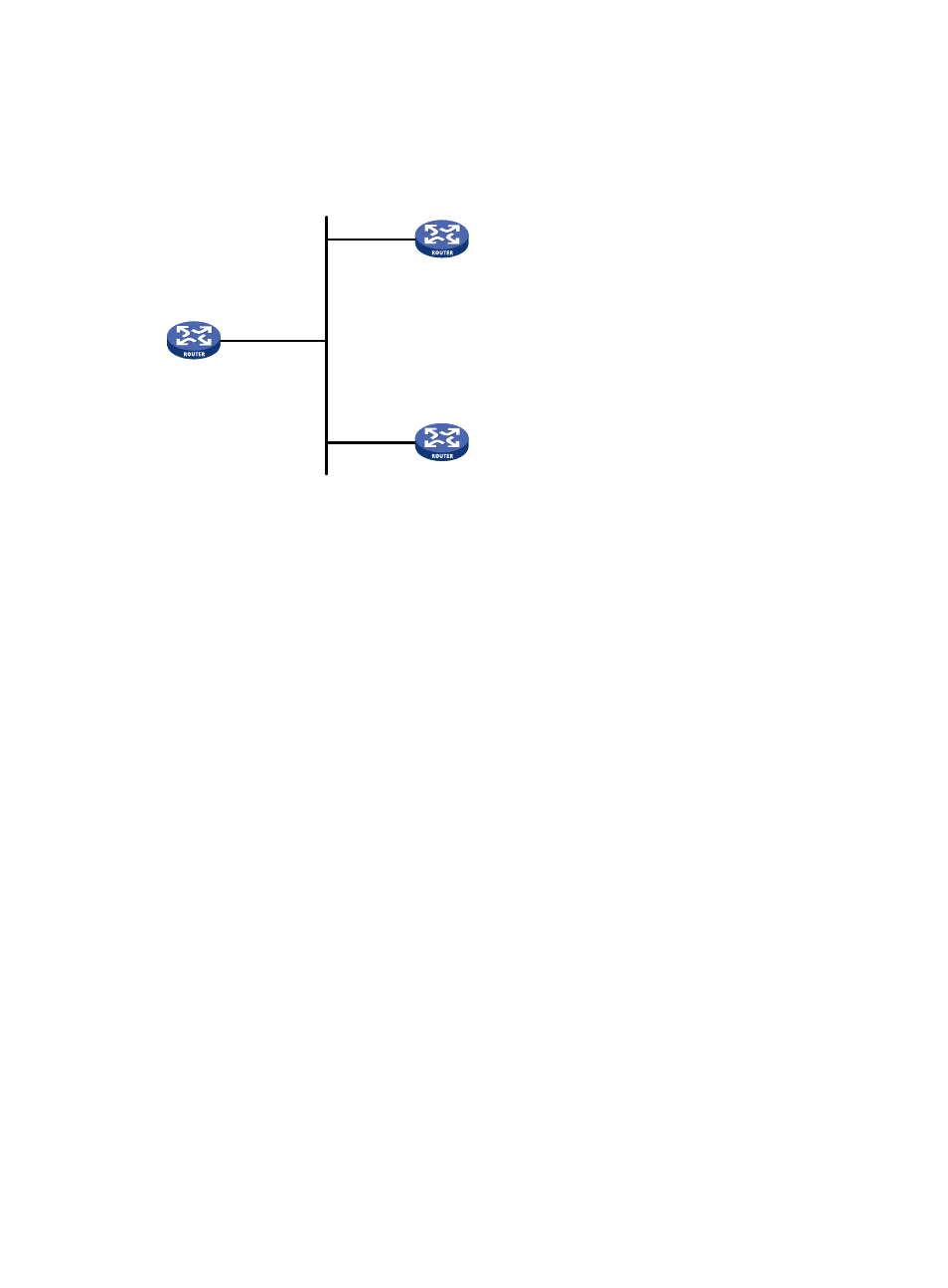
Figure 19 Network diagram
Eth1/1
3.0.1.31/24
Eth1/1
3.0.1.32/24
Router A
Router C
Router B
Eth1/1
3.0.1.30/24
Configuration procedure
1.
Set the IP address for each interface as shown in
. (Details not shown.)
2.
Configure Router C:
# Specify the local clock as the reference source, with the stratum level 2.
[RouterC] ntp-service refclock-master 2
# Configure Router C to operate in broadcast server mode and send broadcast messages through
Ethernet 1/1.
[RouterC] interface ethernet 1/1
[RouterC-Ethernet1/1] ntp-service broadcast-server
3.
Configure Router A:
# Configure Router A to operate in broadcast client mode and receive broadcast messages on
Ethernet 1/1.
[RouterA] interface ethernet 1/1
[RouterA-Ethernet1/1] ntp-service broadcast-client
4.
Configure Router B:
# Configure Router B to operate in broadcast client mode and receive broadcast messages on
Ethernet 1/1.
[RouterB] interface ethernet 1/1
[RouterB-Ethernet1/1] ntp-service broadcast-client
Router A and Router B get synchronized upon receiving a broadcast message from Router C.
# Take Router A as an example. Display the NTP status of Router A after clock synchronization.
[RouterA-Ethernet1/1] display ntp-service status
Clock status: synchronized
Clock stratum: 3
Reference clock ID: 3.0.1.31
45