Configuring poe, Hardware compatibility, Overview – H3C Technologies H3C MSR 50 User Manual
Page 171: Poe configuration task list
Configuring PoE
Hardware compatibility
PoE is available only for MSR 50 routers that are installed with the MPU-G2, and MSR 30-16, MSR 30-20,
MSR 30-40, MSR 30-60, MSR 50-40, and MSR 50-60 routers that are installed with a PoE-capable
switching module.
Overview
IEEE 802.3af-compliant power over Ethernet (PoE) enables a power sourcing equipment (PSE) to supply
power to powered devices (PDs) through Ethernet interfaces over twisted pair cables. Examples of PDs
include IP telephones, wireless APs, portable chargers, card readers, Web cameras, and data collectors.
A PD can also use a different power source from the PSE at the same time for power redundancy.
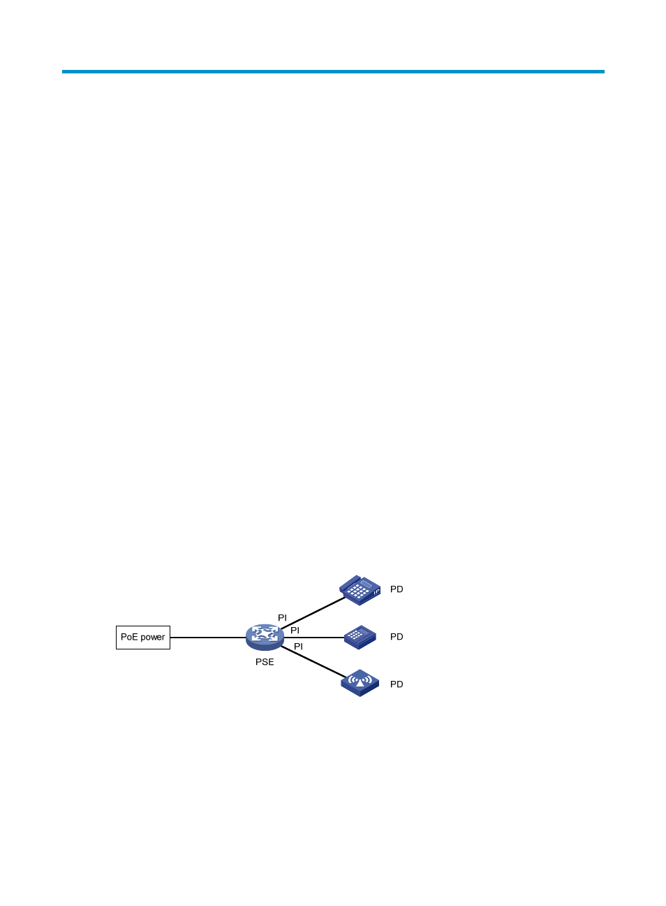
As shown in
, a PoE system comprises the following elements:
•
PoE power—The entire PoE system is powered by the PoE power.
•
PSE—A PSE supplies power to PDs and can also examine the Ethernet cables connected to PoE
interfaces, detect and classify PDs, monitor power supplying state, and detect connections to PDs.
On the device, a PoE-capable interface module is a PSE. The device uses PSE IDs to identify PSEs.
To display PSE ID and interface module slot number mappings, use the display poe device
command.
•
PI—An Ethernet interface with the PoE capability is called a PoE interface. A PoE interface can be
an FE or GE interface.
•
PD—A PD receives power from the PSE. You can also connect a PD to a redundant power source for
reliability.
Figure 54 PoE system diagram
PoE configuration task list
You can configure a PoE interface directly at the CLI or by configuring a PoE profile and applying the PoE
profile to the PoE interface.
158