Dlsw operation configuration example, Network requirements, Configuration procedure – H3C Technologies H3C MSR 50 User Manual
Page 157
Negative SD sum: 1028 Negative DS sum: 1022
Negative SD average: 4 Negative DS average: 5
Negative SD square sum: 495901 Negative DS square sum: 5419
One way results:
Max SD delay: 359 Max DS delay: 985
Min SD delay: 0 Min DS delay: 0
Number of SD delay: 4 Number of DS delay: 4
Sum of SD delay: 1390 Sum of DS delay: 1079
Square sum of SD delay: 483202 Square sum of DS delay: 973651
SD lost packet(s): 0 DS lost packet(s): 0
Lost packet(s) for unknown reason: 0
Voice scores:
Max MOS value: 4.38 Min MOS value: 4.38
Max ICPIF value: 0 Min ICPIF value: 0
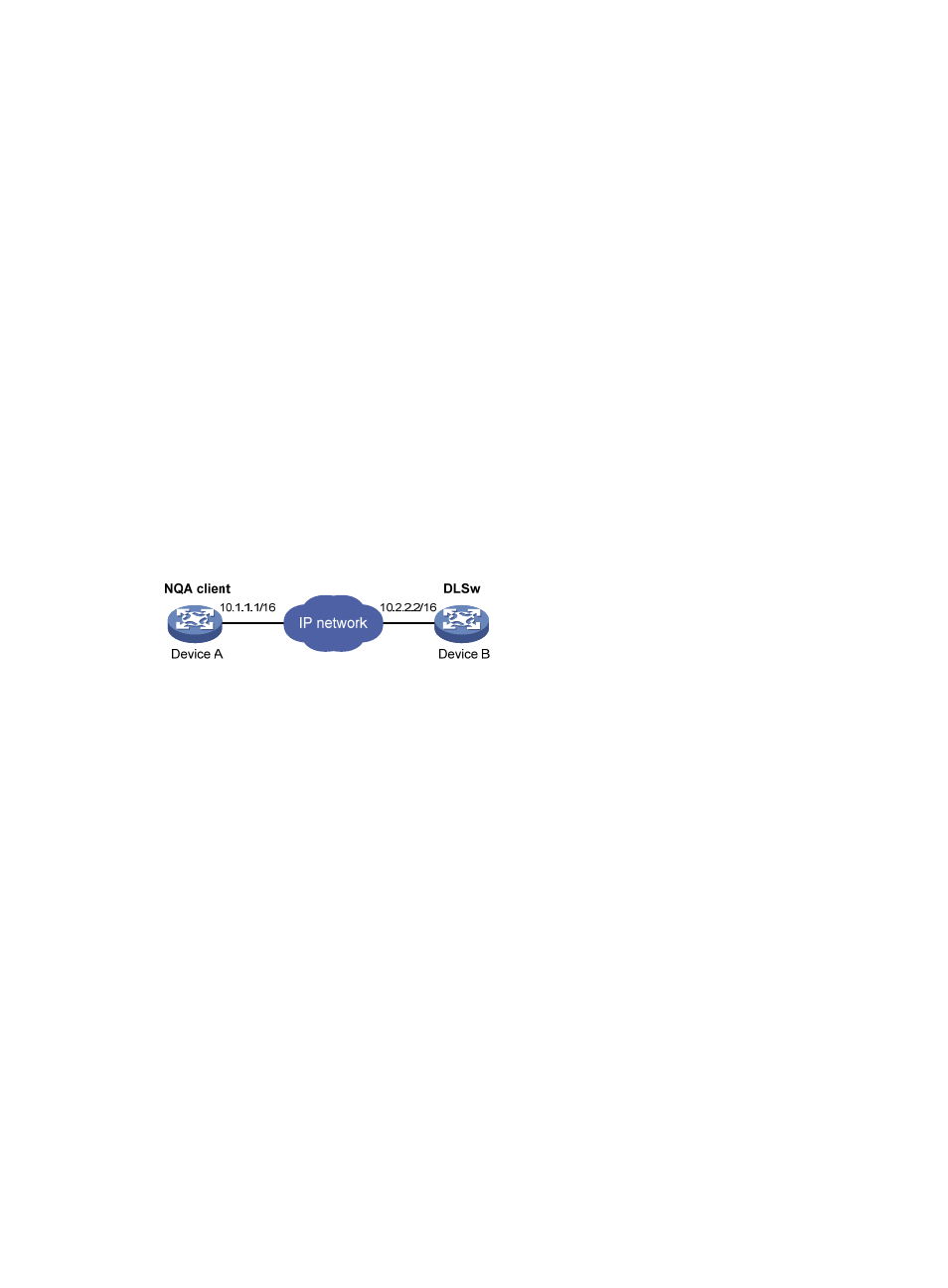
DLSw operation configuration example
Network requirements
As shown in
, configure a DLSw operation to test the response time of the DLSw device.
Figure 48 Network diagram
Configuration procedure
# Assign each interface an IP address. (Details not shown.)
# Configure static routes or a routing protocol to make sure the devices can reach each other. (Details not
shown.)
# Create a DLSw operation, and configure 10.2.2.2 as the destination IP address.
[DeviceA] nqa entry admin test1
[DeviceA-nqa-admin-test1] type dlsw
[DeviceA-nqa-admin-test1-dlsw] destination ip 10.2.2.2
# Enable the saving of history records.
[DeviceA-nqa-admin-test1-dlsw] history-record enable
[DeviceA-nqa-admin-test1-dlsw] quit
# Start the DLSw operation.
[DeviceA] nqa schedule admin test1 start-time now lifetime forever
# Stop the DLSw operation after a period of time.
[DeviceA] undo nqa schedule admin test1
# Display the results of the DLSw operation.
[DeviceA] display nqa result admin test1
NQA entry (admin admin, tag test1) test results:
144