Shaft center line (scl) – Measurement Computing eZ-TOMAS rev.11.0 User Manual
Page 71
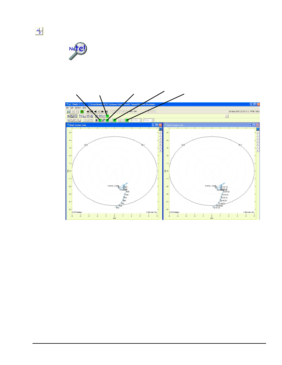
Shaft Center Line (SCL)
Shaft Centerline (SCL) is used to display the change in gap voltage for a Channel Pair. SCL is typically
used in conjunction with Displacement Probes.
In order to get valid SCL displays the input channels must be DC coupled.
The measured DC Gap Voltage is corrected to the Gap Reference Value and Shaft Starting Location
(Brg Start), which are set in the Edit pull-down menu’s Setup Configuration window, in the Input
Channels tab.
Display Shaft
Cursor Centerline Cursor Update Annotation Overlay Bearing
Values Display (Peak Search) Clearance Circle
eZ-TOMAS
937594
Display Menu … Plots Plot Examples 7-9
Shaft Centerline Displays with Annotation
In this figure the plot at the left has focus.
The movement of the shaft centerline [towards the probe] can be easily calculated by dividing the change
in Gap Voltage by the Displacement Probe’s sensitivity. An example follows.
Example:
Machine running: Gap Voltage (GV
1
) is -9 VDC
Machine at rest: Gap Reference Voltage (GV
2
) is -10 VDC
Delta Gap Voltage: (GV
1
– GV
2
) is 1 VDC
Probe Sensitivity (S): 200 mV/mil
SCL movement equals Delta Gap Voltage divided by Probe Sensitivity, therefore:
Movement = (GV
1
– GV
2
) / S
= 1VDC / (200 mV/mil)
= 5 mil
Note: 1 mil = 0.001 inch, or 25.4 µm