Using “initialize project – Measurement Computing eZ-TOMAS rev.11.0 User Manual
Page 16
Using “Initialize Project”
If you have multiple hardware modules, and change the number of Input Channels, you
need to use the initialize function to create a new eZ-TOMAS Project. This needs to be
done once, for the first implementation of the new hardware setup. An explanation of
how to access and use the Initialize Project function follows.
When a project is initialized you are essentially starting with a “clean slate.” No data is
carried over, as would be when a project is cloned as discussed on page 2-4.
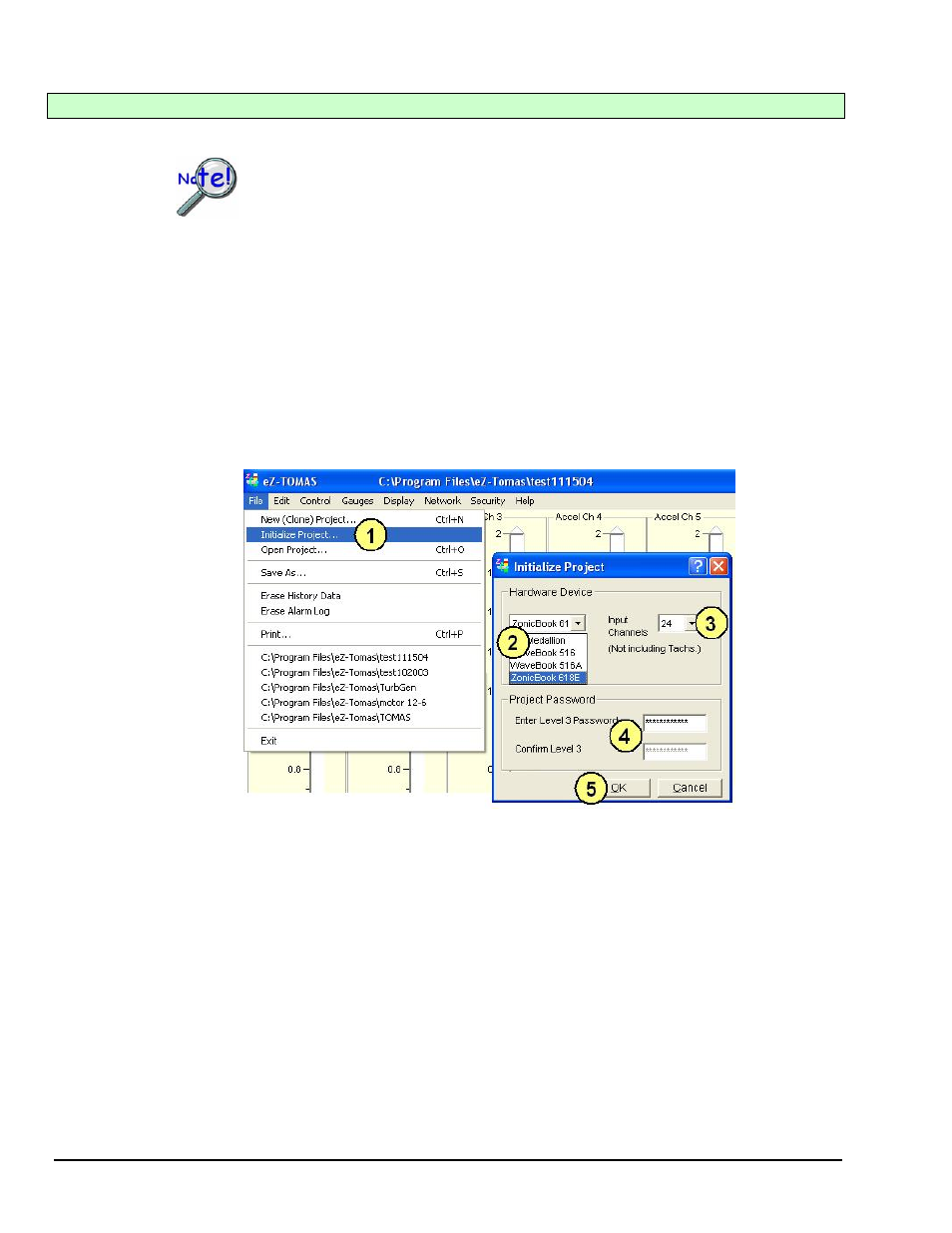
“Initialize Project” is accessed from the File pull-down menu. Initialize Project provides a means of
selecting the hardware device and setting the number of input channels. For example: If you had an 8
channel Medallion and were going to change your acquisition to 24 channels, for example, using a
ZonicBook/618E and two WBK18 modules, you would need to use the Initialize Project feature.
Complete the following steps to initialize a project. Note that the step numbers correspond to the numbers
in the figure.
1. From the File pull-down menu, open “Initialize Project.” An Initialize Project dialog will open.
2. Select the Hardware Device from the associated pull-down list.
3. Select the number of analog input channels from the associated pull-down list. For
ZonicBook/618E do not count the separate tach channels as input channels.
4. If applicable, enter and confirm the project password.
5. Click the
Staying with our 24 channel example [using a ZonicBook/618E and two WBK18 modules], the gauge panel
will now appear with three rows of data beneath the gauges (see following figure). Each row will have 8
data cells (one per input channel). Note that the gauge panel can display up to 7 rows of data, thus
accomodating 56 channels.
Only 8 gauges can be displayed at a time, but the cells allow you to choose which gauges to view, as will
be seen in the following three figures and related text.
Note: For greater clarity in the following three figures, gauges have been compressed vertically and several
gauges have been removed, e.g., channels 5, 6, and 7 for Fig 1; channels 13, 14, and 15 for Fig. 2; and
channels 21, 22, and 23 for Fig. 3.
2-2 Monitoring a Machine
987294
eZ-TOMAS