Digital i/o configuration, Hardware panel, Digital i/o channels panel – Measurement Computing eZ-TOMAS rev.11.0 User Manual
Page 46
Digital I/O Configuration
Hardware Panel
The top panel of the Digital I/O Configuration Window is the Hardware panel (see following figure).
To ensure proper output:
(1) An NDTRelay must be connected as indicated in separate NDTRelay documentation.
(2) The relay’s model number must be indicated in eZ-TOMAS’s Digital I/O
Configuration window.
(3) The applicable COM Port must be identified.
Model Number: Select the applicable output relay module: NDTRelay1 or NDTRelay2.
RS 232 COM Port: Select the COM (serial) Port to which the output Relay module is connected.
Time (seconds)
that the Digital
Output is to be
Active
Action Selected
(from pull-down
list) for Digital
Input
Sets the Digital
Output’s Normal
State to “Opened”
or “Closed”
Digital Input
is Selected
Digital Output
is Selected
Enable/Disable
Digital I/O
Alarm Event for
Digital Output
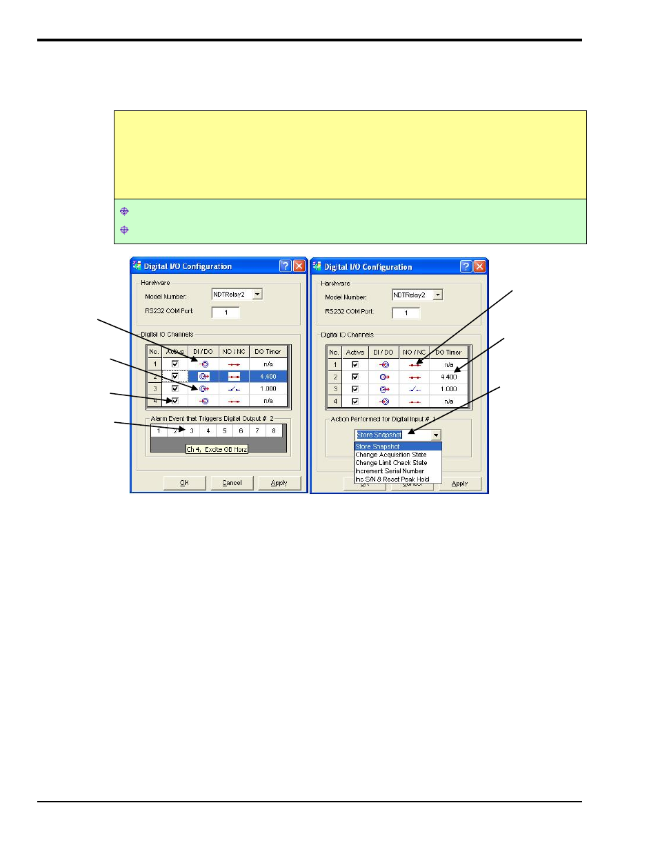
Digital I/O Configuration, Accessible from the Edit Pull-Down Menu (2 views)
The panel below the Digital I/O Panel will be an Alarm Event panel for Digital Output channels, as indicated in the
left-hand image; and will be an Action Performed panel for Digital Input channels, as indicated in the right-hand
image.
Digital I/O Channels Panel
The second panel of the Digital I/O Configuration window is the Digital I/O Channels panel. There are
four Digital I/O channels, each of which can be configured for digital input or digital output. As seen in the
above figure [which shows a Digital Output example on the left and a Digital Input example on the right].
Each of the 4 channels has a Checkbox that is used to enable or disable the digital I/O function of the
channel. A checkmark in the box indicates that the channel is active.
•
•
•
The “DI / DO” column is used to select Digital Input or Digital Output. Clicking on the small
schematic icon (in the column) toggles between the two options, i.e., Input and Output and displays an
associated image. The arrow going into a connector represents Digital Input, the arrow leaving the
connector represents Digital Output.
The “NO / NC” column refers to the normal state of the Digital Output. The normal state can be set to
be Normally Opened or Normally Closed on limit/alarm status. You can use up to four relays. A blue
line, showing an open between two points is used for Normally Open. A red line, connecting two
points, is used for Normally Closed.
4-18 Edit Menu
947394
eZ-TOMAS