Preassembly – Harken 1036 MKIII Jib Reefing & Furling User Manual
Page 21
Preassembly
How many foils and connectors • Stringing connectors
May 2002
Unit 3 MKIII
11
Pin-to-Pin Headstay Length (See Pg 8)
Longueur axe à axe de l’étai (Voir Pg 8)
Bolzen-Bolzen-Mass Anzahl des Vorstages (s.S. 8)
Lunghezza perno-a-perno dello strallo (vedi p. 8)
Number 10" (254 mm) Connectors
Nombre de connecteurs de 254 mm utilisés
Verbindungselements
Numero di estrusi da 254 mm usati
53'7" to 54'7" (16.332 m to 16.637 m)
7
54'8" to 61'7" (16.654 m to 18.771 m)
8
61'8" to 68'7" (18.796 m to 20.904 m)
9
68'8" to 75'7" (20.930 m to 23.038 m)
10
75'8" to 81'7" (23.063 m to 24.867 m)
11*
Number 7' (2.13 m)Foils Used
Nombre de profils de 2.13 m utilisés
Verbindungselements
Numero di estrusi da 2.13 m usati
53'7" to 60'8" (16.332 m to 18.491 m)
7
60'9" to 67'8" (18.517 m to 20.625 m)
8
67'9" to 74'8" (20.650 m to 22.758 m)
9
74'9" to 81'7" (22.784 m to 24.867 m)
10*
■ How Many Connectors?
Use the chart at left to determine the proper number
of 10" (254 mm) connectors for your headstay.
Every unit uses one 13" (330 mm) bottom connector
in addition to the number of 10" (254 mm) connectors
shown at left.
*One additional connector required; order part 960 for
7
/
16
",
1
/
2
", 11 mm, 12 mm, or -30 rod; order part 997
for -22 rod
■ How Many Foils?
Use the chart at left to determine the proper number
of 7’ (2.13 m) foils for your headstay.
The variable length top foil is cut from one of the 7’
(2.13 m) foils and is used in addition to the number
of foils shown at left.
*One additional foil required; order part 958
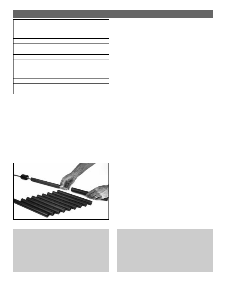
■ Stringing Connectors
After the headstay has been cut to length, but before the
swage stud is attached, the proper number of connectors
must be placed on the headstay in the correct order.
Every unit uses a top foil trim cap.
Every unit uses a number of 10" (254 mm) connectors
which varies according to the length of the headstay
and is determined by consulting the chart above.
Every unit uses one 13" (330 mm) bottom connector
Slide the trim cap onto the stay so that the open end
faces down.
Slide the proper number of 10" (254 mm) connectors
onto the headstay.
Slide the 13" (330 mm) bottom connector onto the
headstay so that it is closest to the bottom of the
headstay.
Have the wire swaged by a reputable rigger.
Connectors used for -22 rod must have plastic bushings
to decrease the connector bore. Bushings are shipped
with the -22 rod terminal along with instructions for
installing them in the connectors.
Norseman/Sta-Lok Instructions
Because Norseman and Sta-Lok studs are applied to the
headstay wire after the foil is built, it is not necessary to
place the connectors or trim cap on the wire at this time.
Norseman and Sta-Lok units require the same number of foils
and connectors as shown above. Identify the parts you need
and set them aside at this time.
Rod Instructions
Rod installations are identical to swaged wire at this point
except that the rod fitting is “coldheaded” to the rod rather
than swaged on.
If you ship a rod headstay to a service center do not coil tighter
than 200 times the rod’s diameter.