Comtech EF Data SDM-9000 User Manual
Page 60
Configuration
SDM-9000 Satellite Modem
3–2
Rev. 4
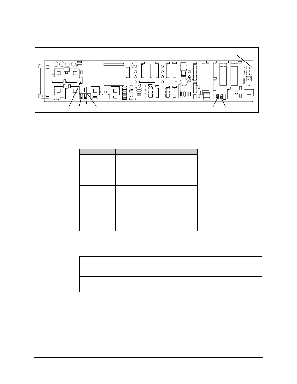
JP2
JP3
JP1
JP5
JP9
JP10
ASSEMBLY NUMBER AND
SERIAL NUMBER
Figure 3-1. Display/M&C PCB
Table 3-1. Display/M&C PCB Jumper Settings
Jumper
Position
Function
JP1
1 to 2
3 to 4
5 to 6
7 to 8
RS-485 Remote
RS-485 Remote
RS-232-C Remote
RS-232-C Remote
JP2
(See Note
)
1 to 2
2 to 3
4-Wire
2-Wire
JP3
(See Note)
1 to 2
2 to 3
4-Wire
2-Wire
JP5
1 to 2
2 to 3
RS-485 Remote
RS-232-C Remote
JP9 and JP10
32K
64K
128K
256K
256K
27C256 EEPROM at U17
27C512 EEPROM at U17
27C010 EEPROM at U17
27C020 EEPROM at U17
27C040 EEPROM at U17
Note: Pins JP2 and JP3 must be in the 4-wire position for RS-232-C.
RS-485 Configuration
Install two jumpers (shunts) at the RS-485 positions of JP1, and
install one jumper at the RS-485 position of JP5.
For 2- or 4-wire operation, position jumpers at JP2 and JP3 to the
designated positions.
RS-232-C Configuration
Install two jumpers (shunts) at the RS-232-C positions of JP1, and
install one jumper at the RS-232-C position of JP5.
Install jumpers at JP2 and JP3 for 4-wire operation.
- CDD-880 (124 pages)
- CDM-800 (130 pages)
- ODMR-840 (184 pages)
- CDM-750 (302 pages)
- CDM-840 (244 pages)
- SLM-5650A (420 pages)
- CTOG-250 (236 pages)
- CDM-700 (256 pages)
- CDM-760 (416 pages)
- CDM-710G (246 pages)
- CDM-600/600L (278 pages)
- CDMR-570L (512 pages)
- CDM-625 (684 pages)
- CDM-625A (756 pages)
- CDD-564A (240 pages)
- CDD-564L (254 pages)
- CLO-10 (134 pages)
- MCED-100 (96 pages)
- CDMR-570AL (618 pages)
- CDM-600 LDPC (2 pages)
- BUC Power Supply Ground Cable (2 pages)
- MPP70 Hardware Kit for CDM-570L (4 pages)
- MPP50 Hardware Kit for CDM-570L (4 pages)
- CDM-625 DC-AC Conversion (4 pages)
- CDM-625 DC-AC Conversion with IP Packet Processor (4 pages)
- DMDVR20 LBST Rev 1.1 (117 pages)
- DMD2050E (212 pages)
- DMD-2050 (342 pages)
- DMD1050 (188 pages)
- OM20 (220 pages)
- QAM256 (87 pages)
- DD240XR Rev Е (121 pages)
- MM200 ASI Field (5 pages)
- DM240-DVB (196 pages)
- MM200 (192 pages)
- CRS-150 (78 pages)
- CRS-280L (64 pages)
- CRS-170A (172 pages)
- CRS-180 (136 pages)
- SMS-301 (124 pages)
- CiM-25/8000 (186 pages)
- CiM-25 (26 pages)
- CRS-500 (218 pages)
- CRS-311 (196 pages)
- CIC-20 LVDS to HSSI (26 pages)