4 external connectors – Comtech EF Data SDM-9000 User Manual
Page 47
SDM-9000 Satellite Modem
Installation
Rev. 4
2–5
2.4 External Connectors
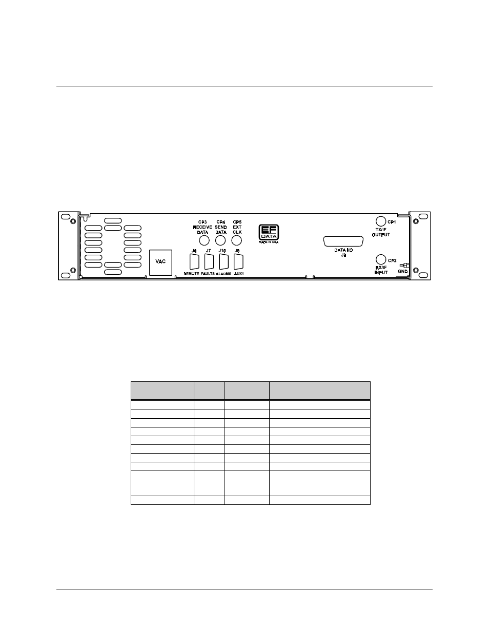
When a breakout panel is not required, the external modem connections between the
modem and other equipment are made through several rear panel connectors. These
connectors are shown in Figure 2-2, and their locations are listed in Table 2-1. The
connectors are described in the following paragraphs.
When a B141-1 breakout panel is required, refer to the B141-1 Breakout Panel
Installation and Operation Manual for connector information.
Figure 2-2. SDM-9000 Rear Panel View
Note: In order to meet the European EMC Directive (EN55022, EN50082-1), properly
shielded cables for DATA I/O are required. These cables must be double-shielded from
end to end, ensuring a continuous ground shield.
Table 2-1. Modem Rear Panel Connectors
Name
Ref.
Desig.
Connector
Type
Function
TX/IF OUTPUT
CP1
BNC
RF output
RX/IF INPUT
CP2
BNC
RF input
RECEIVE DATA
CP3
BNC
RX terrestrial data input
SEND DATA
CP4
BNC
TX terrestrial data input
EXT CLK
CP5
BNC
External clock input
REMOTE
J6
9-pin D
Remote interface
FAULTS
J7
9-pin D
Form C fault relay contacts
DATA I/O
J8
50-pin D
Data I/O (ESC)
AUX1
J9
9-pin D
TTL faults
External reference
AGC output
ALARMS
J10
9-pin D
Form C alarm relay contacts