A.1.2.2 reed-solomon decoder – Comtech EF Data SDM-9000 User Manual
Page 191

SDM-9000 Satellite Modem
Options
Rev. 4
A–5
A.1.2.2 Reed-Solomon Decoder
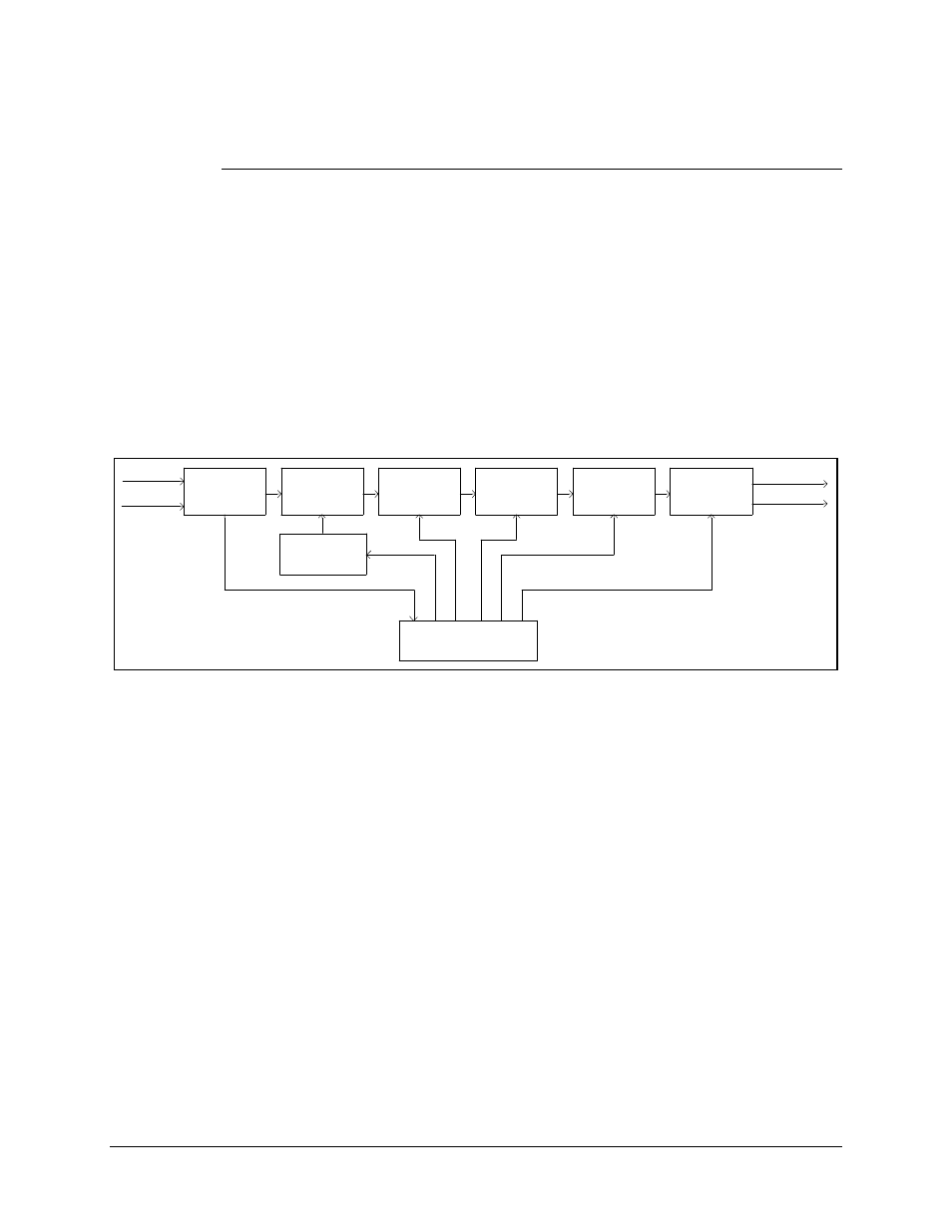
A block diagram of the Reed-Solomon decoder section is shown in Figure A-4. The
Reed-Solomon decoder section includes the following circuits:
•
3-channel serial unique word corrolater
•
RAM interleaver
•
Input FIFO
•
Reed-Solomon decoder
•
Output FIFO
•
8-bit parallel descrambler
JP2
JP2
DESCRAMBLER
JP2
DEMUXDAT
(SERIAL)
DEMUXCLK
U9
OUTPUT
FIFO
U10
RS CODEC
(DECODER
SECTION)
U16
INPUT
FIFO
U16
RAM
DEINTERLEAVER
U16
8 BIT PARALLEL
UNIQUE WORD
3 CHANNEL
SERIAL
CORROLATER
JP2
RXSATDAT
RXSATCLK
U9
RS TIMING
U15
DEINTERLEAVER
ADDRESS
GENERATOR
U15
CONTROLLER
(SERIAL)
Figure A-4. Reed-Solomon Decoder Section Block Diagram
The three channels of serial data and the clock signals come from the demultiplexer on
the interface PCB and are sent to the Reed-Solomon decoder section through connector
JP3.
The data is passed to a 3-channel serial corrolater which locates the unique words and
reformats the data to 8 bits on the appropriate byte boundaries.
Because the data was block interleaved by the encoder, data must pass through a de-
interleaver with the same depth as the interleaver used on the encoder. The de-interleaver
is synchronized by the detection of the unique words which are placed at the end of each
RS frame by the interleaver on the encoder. Once the de-interleaver is synchronized to
the incoming data, the data is reassembled into its original sequence in accordance with
the IESS-308 Rev. 6B specification. The data is then sent to the input FIFO and on to the
Reed-Solomon decoder.
