A.2.2 baseband physical interfaces, A.2.2.1 ecl physical interface – Comtech EF Data SDM-9000 User Manual
Page 198

Options
SDM-9000 Satellite Modem
A–12
Rev. 4
A.2.2 Baseband Physical Interfaces
The baseband physical interface for the DBS mode is provided by the Emitter Coupled
Logic (ECL) or Positive Emitter Coupled Logic (PECL) interface boards installed in the
SDM-9000. Refer to Sections A.2.2.1 and A.2.2.2 for information about the respective
interface boards.
Characteristics of the baseband physical interface are described in Section A.2.3.
Timing requirements for the baseband physical interface are presented in Section A.2.4.
A.2.2.1 ECL Physical Interface
The ECL interface uses MC10H115 differential line receivers and MC10H101
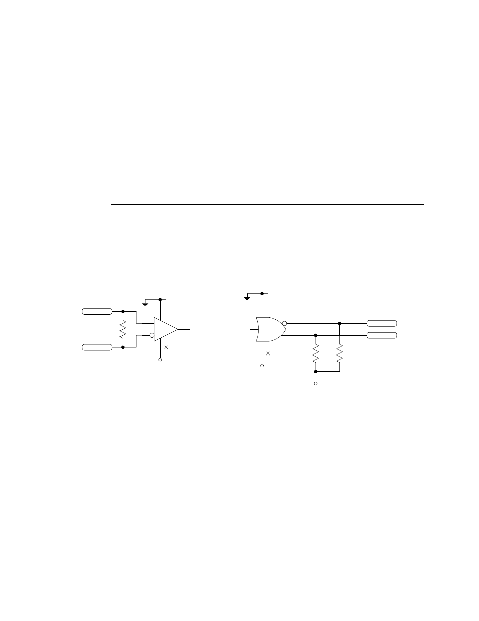
differential line drivers to provide the electrical interface to the SDM-9000. Figure A-7
shows a typical differential ECL receiver and driver diagram.
5
2
1
16
8
12
4
MC10H101
5
4
2
1
16
8
9
MC10H115
100
+ECL_IN
-ECL_IN
-5.2V
-5.2V
330
-ECL_OUT
+ECL_OUT
330
-5.2V
Figure A-7. Typical Differential ECL Receiver and Driver
- CDD-880 (124 pages)
- CDM-800 (130 pages)
- ODMR-840 (184 pages)
- CDM-750 (302 pages)
- CDM-840 (244 pages)
- SLM-5650A (420 pages)
- CTOG-250 (236 pages)
- CDM-700 (256 pages)
- CDM-760 (416 pages)
- CDM-710G (246 pages)
- CDM-600/600L (278 pages)
- CDMR-570L (512 pages)
- CDM-625 (684 pages)
- CDM-625A (756 pages)
- CDD-564A (240 pages)
- CDD-564L (254 pages)
- CLO-10 (134 pages)
- MCED-100 (96 pages)
- CDMR-570AL (618 pages)
- CDM-600 LDPC (2 pages)
- BUC Power Supply Ground Cable (2 pages)
- MPP70 Hardware Kit for CDM-570L (4 pages)
- MPP50 Hardware Kit for CDM-570L (4 pages)
- CDM-625 DC-AC Conversion (4 pages)
- CDM-625 DC-AC Conversion with IP Packet Processor (4 pages)
- DMDVR20 LBST Rev 1.1 (117 pages)
- DMD2050E (212 pages)
- DMD-2050 (342 pages)
- DMD1050 (188 pages)
- OM20 (220 pages)
- QAM256 (87 pages)
- DD240XR Rev Е (121 pages)
- MM200 ASI Field (5 pages)
- DM240-DVB (196 pages)
- MM200 (192 pages)
- CRS-150 (78 pages)
- CRS-280L (64 pages)
- CRS-170A (172 pages)
- CRS-180 (136 pages)
- SMS-301 (124 pages)
- CiM-25/8000 (186 pages)
- CiM-25 (26 pages)
- CRS-500 (218 pages)
- CRS-311 (196 pages)
- CIC-20 LVDS to HSSI (26 pages)
