A.2.3 dbs baseband interface, A.2.3.2 dbs rx baseband interface – Comtech EF Data SDM-9000 User Manual
Page 200

Options
SDM-9000 Satellite Modem
A–14
Rev. 4
A.2.3 DBS Baseband Interface
A.2.3.1 DBS TX Baseband Interface
As illustrated previously by Figure A-6, the data and sync inputs are first passed through
a dejitter FIFO register to hand off the data to the stable transmit clock, and then passed
to the SYNC 1 inversion and scrambler block.
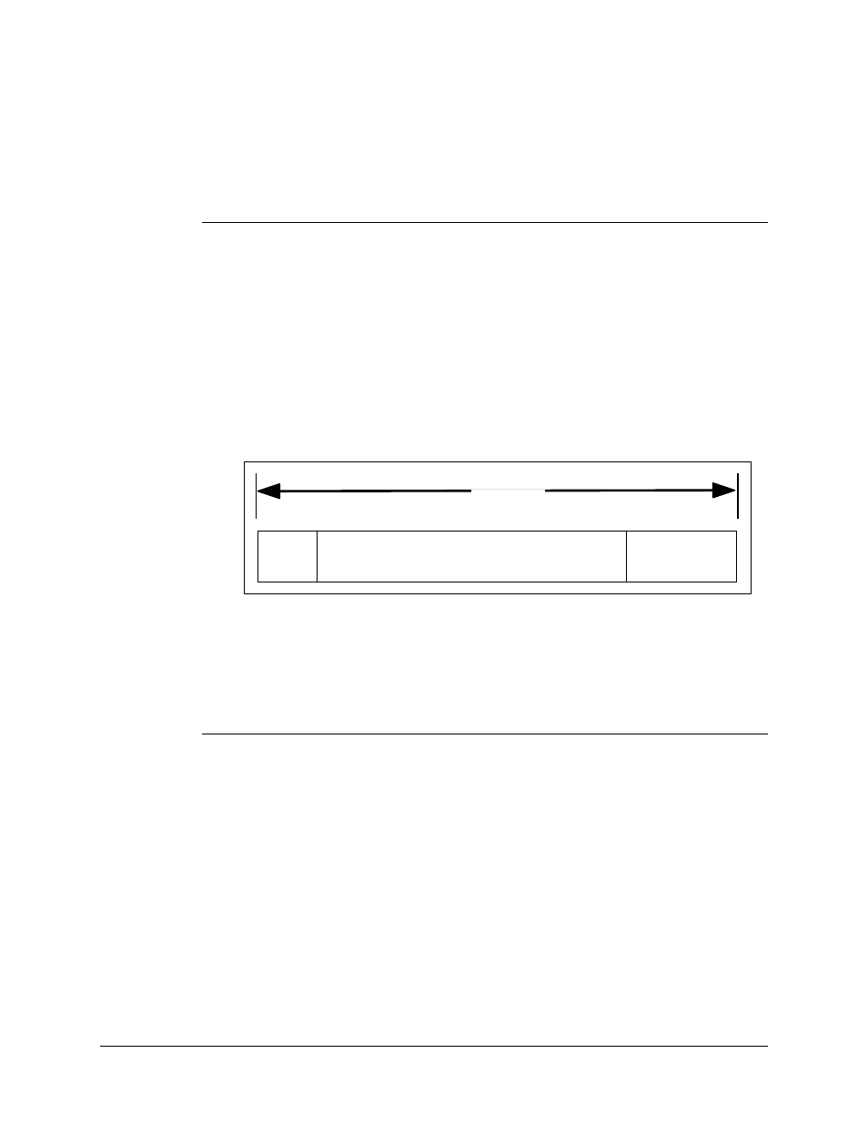
The transmit DBS baseband interface accepts data in 204-byte packets in bit serial
format that are composed of 188-byte MPEG-2 packets. In addition, 16 null bytes are
included as place holders for Reed-Solomon overhead. Figure A-9 shows the packet
arrangement.
204 BYTES
(1,632 BITS)
SYNC
BYTE
PAYLOAD (187 BYTES)
ZERO PADDING
16 BYTES
Figure A-9. DBS Mode Baseband Packet
Note: An additional sync input is used to indicate the position of the sync byte within the
input stream.
A.2.3.2 DBS RX Baseband Interface
The receive DBS baseband interface takes data and sync pulses from the SYNC 1
inversion logic, and provides bit serial data and sync pulses in 204-byte packets
(1,632 bits) to the outside world.
